
Five-pin Magnetic Connectors: Layout, Integration and Buying Guide
Published on July 31, 2026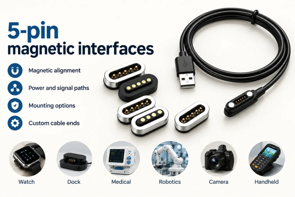
- A Five-contact Magnetic Interface
- The Mating Sequence
- Other Five-contact Connector Families
- Assigning the Five Contacts
- Benefits for Product Integration
- Specifications and Alternatives
- Cost and Procurement
- Five-contact Design Questions
Five contacts provide room for power, data, sensing or control in a magnetically guided interface. This guide covers mating, contact assignments, current capability, mounting, sealing, applications and selection requirements for engineering and procurement.
A Five-contact Magnetic Interface
A five-pin magnetic connector combines five conductive contacts with magnetic guidance. Pogo pins or other spring contacts carry power, signals or a chosen combination, while the magnets assist quick attachment and alignment in compact products.
5 Pin Magnetic Connector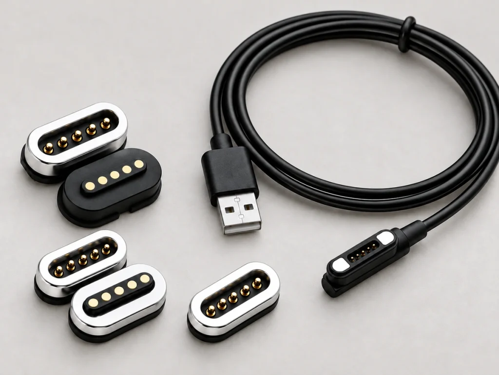
Core Definition and Structure
The five-contact layout allows the circuit designer to allocate power, data, detection, ground and communication functions as required. Electrical stability depends on the complete interface, not on the contact count alone.
A common arrangement pairs spring-loaded pins with copper-alloy mating contacts. Magnetic attraction guides the halves together and can reduce insertion effort and wear relative to suitable plug-in alternatives. The result depends on the contact and housing design.
The table describes common structural elements; confirm materials for the selected model.
| Component | Function | Typical Material or Design |
|---|---|---|
| Pogo pins | Transfer current or signal | Gold-plated brass or copper alloy |
| Magnets | Provide automatic alignment and retention | NdFeB magnets |
| Housing | Protects and positions contacts | Plastic, metal, or hybrid shell |
| Mating contact / pad | Mating surface for pogo pins | Gold-plated copper alloy |
Scroll horizontally to view every column.
For frequently docked products, five-contact pogo interfaces can support blind mating and compact layouts. Sealing, reverse-mating protection and higher current capability are possible custom requirements, rather than standard features of every five-pin part.
Design note: Allocate the electrical roles before fixing the shape. Clear current, signal and return requirements make it easier to select dimensions, retention and plating.
The Mating Sequence
As the correctly oriented halves approach, magnets draw them toward the mating position. The pogo contacts compress against their pads and complete the five assigned conductive paths. Those contacts do not necessarily form five separate complete circuits.
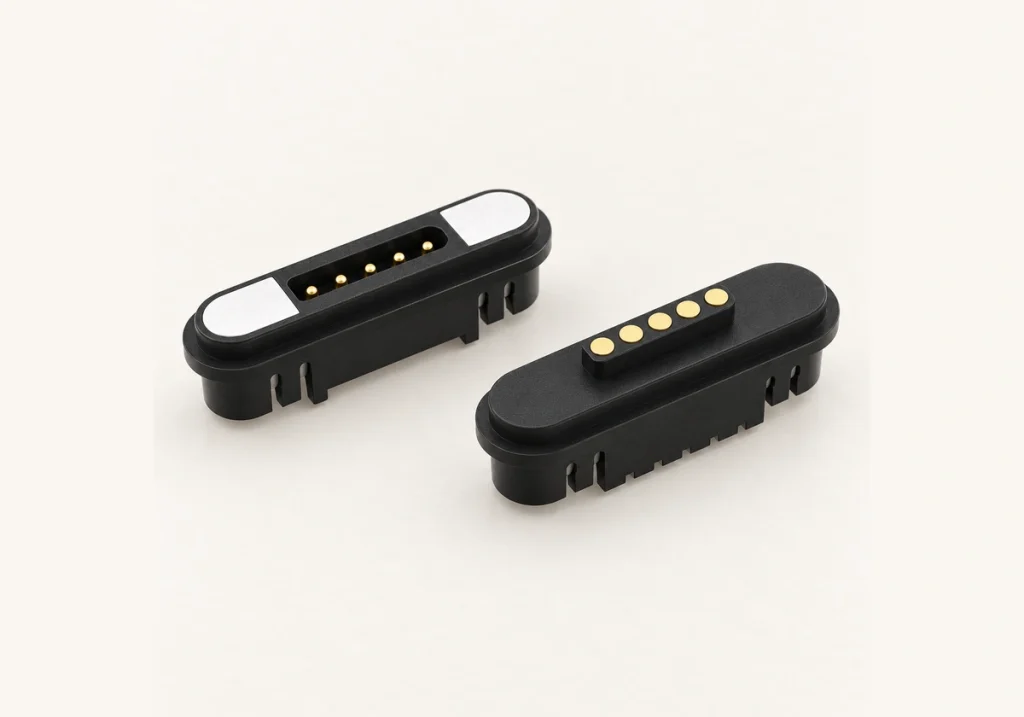
Working Principle and Contact Sequence
Magnets position and retain the assembly, while spring contacts supply mating pressure. Validate that pressure through the specified working travel, dimensional variations, vibration and cycling conditions.
A typical connection process includes:
Approach: Bring the two mating halves closer.
Alignment: Attraction guides the correctly oriented halves toward their mating position.
Seating: Housing geometry controls the final contact position and load.
Compression: Spring contacts compress within their working travel and develop contact pressure.
Conduction: The five contacts carry their assigned power, signal, return or control functions.
Release: The pair can detach under a designed pulling force; validate direction and force to control stress on the device port.
Magnetic guidance can reduce the need for precise manual plug insertion and the stress associated with it. Consumer and industrial products may benefit in handling and service life, but comparisons need equivalent use conditions.
For power, verify current capability, spacing, temperature rise and short protection. For signals or data, also evaluate resistance, shielding, signal integrity and the contact assignment.
Design note: Contact mating can reduce insertion wear. Designs intended for tens of thousands or even hundreds of thousands of cycles need model-specific testing under defined load, travel, environment and resistance limits; those figures are not a rating for every five-pin connector.
Other Five-contact Connector Families
Five-contact options include magnetic pogo interfaces, circular connectors sometimes called aviation connectors, DIN families, JST-style wire connectors, board-to-board parts and sealed charging interfaces. Magnetic guidance is one option when fast docking, frequent mating and compact packaging matter; the category labels can overlap.
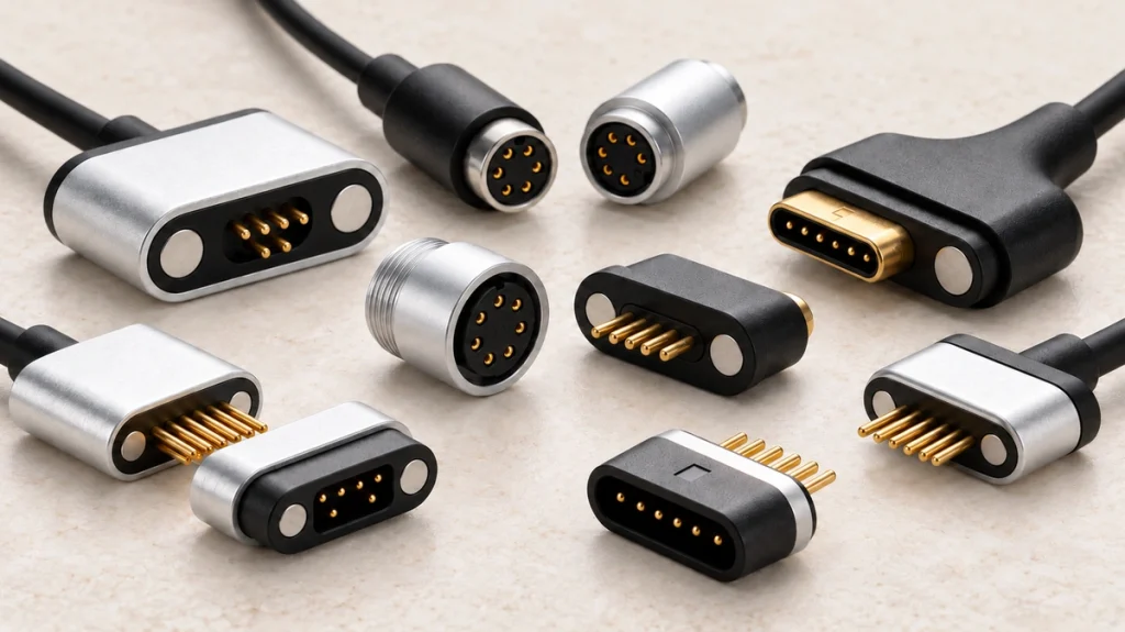
Common Types and Application Differences
The phrase “five-pin connector” describes contact count across several families. Choose against docking needs, cable or PCB integration, sealing and mechanical retention, rather than assuming equivalent interfaces.
This overview compares broad families and their typical design trade-offs.
| Connector Type | Main Use | Strength | Limitation |
|---|---|---|---|
| 5 Pin Magnetic Connector | Charging docks, wearables, handheld devices | Fast alignment, easy connection, compact | Requires magnetic and polarity design |
| 5 pin magnetic pogo connector | Power and signal docking | Reliable spring contact, customizable | Needs controlled contact force |
| 5-pin circular connector | Industrial sensors, control systems | Strong locking and durability | Larger size |
| 5-pin DIN connector | Audio, legacy equipment, control interfaces | Standardized layout | Less compact for modern devices |
| 5-pin wire-to-board connector | Internal wiring | Low cost, secure assembly | Not ideal for frequent external mating |
| 5-pin board-to-board connector | PCB stacking | High-density internal connection | Limited user accessibility |
| Waterproof 5-pin connector | Outdoor electronics, marine devices | Sealed and rugged | Higher tooling and material cost |
Scroll horizontally to view every column.
A five-contact magnetic pogo interface can form part of the user interaction in rechargeable medical devices, locks, portable instruments, GPS trackers and IoT terminals. These are possible applications, not evidence of a specific customer or device approval.
A mechanically locked conventional interface may better suit a long-term installed connection. Magnetic mating may suit frequent use where convenience and quick release take priority; compare the requirements of the actual product.
Magnetic connectorsDesign note: Matching contact count does not establish matching ratings. Two five-pin designs can differ in current, sealing, cycling life and assembly method.
Assigning the Five Contacts
Configuration includes each contact’s role, pitch, orientation and electrical capability. A magnetic five-contact layout can allocate power, return, data, detection and control, with protection against reverse mating, shorts and unwanted signal coupling designed into the complete system.
Pin Assignment and Layout Options
Allocate the contacts to the device’s electrical architecture. Some designs need additional power contacts; others need communication or detection. Coordinate the pinout with magnetic polarity and the mechanical mating orientation.
The following is an example assignment, rather than a universal pinout:
| Pin | Example Function | Design Notes |
|---|---|---|
| Pin 1 | VBUS / Positive power | Rated for required charging current |
| Pin 2 | Ground | Often paired with power return |
| Pin 3 | Data positive / Signal | Used for communication or sensing |
| Pin 4 | Data negative / Control | Used for differential signal or control |
| Pin 5 | Detection / ID / Auxiliary | Confirms docking or accessory type |
Scroll horizontally to view every column.
Other assignments are possible. A high-current design might use two positive and two return contacts to reduce resistance and heating, leaving one for detection or communication. Validate current sharing and thermal performance before using parallel contacts.
Key configuration factors include:
Pin pitch: Affects size, safety distance, and manufacturability.
Current rating per pin: Determines whether pins need to be paralleled.
Contact resistance: Impacts voltage drop and heat generation.
Magnet polarity: Supports the intended orientation or alignment when designed with appropriate mechanical guidance.
Waterproof structure: Requires sealing around contacts and housing.
PCB footprint: Must match soldering, assembly, and enclosure constraints.
PCB
Limit exposed live contacts where practicable. Recessed contacts, staged contact lengths, circuit protection or device-side power control can reduce risk, but require system-level verification.
Design note: Contact functions can be adapted to the device. Power or data contacts may also need individually engineered geometry and ratings; agree the specification for each path.
Benefits for Product Integration
Potential benefits include quick guided mating, less insertion wear, compact packaging, controlled breakaway and flexible contact assignment. These can be useful in frequently charged products where simple handling, sealing or a clean external design matters, subject to the completed interface’s performance.
Practical Advantages for Device Design
Magnetic attachment can ease alignment for the user. Wearables, medical electronics, smart home products and handheld industrial terminals may benefit, provided contact reliability and handling are validated for the product.
Main benefits include:
Quick mating: Magnetic attraction helps the connector snap into place.
Reduced port damage: No deep insertion mechanism is required.
High mating cycle potential: Pogo pins are suitable for frequent docking.
Pogo pinsCompact integration: Low-profile designs support small devices.
Controlled breakaway: A designed release can reduce the risk of pulling the device over; verify force and direction.
Custom pin functions: Five pins can support charging, data, ID, and control.
Sealing choices: Consider suitable adhesive, silicone O-rings or molded integration, with assembly-level sealing tests.
Accessible handling: Assess use with gloves, reduced lighting or limited dexterity, including older users, in the intended product.
Customization can address shape, pin height, magnetic retention, plating thickness, current capability, cable length, PCB footprint and sealing requirements.
A suitable interface can support a refined product feel and reduce service problems related to damaged ports or difficult insertion. Treat those benefits as design goals to verify, rather than guaranteed outcomes.
Design note: For frequent charging, use lifecycle testing that reproduces the product’s operating conditions. Performance in a normal environment does not establish performance under severe exposure; include the actual environmental loads in the test plan.
Specifications and Alternatives
A five-contact magnetic interface combines guided alignment, spring contacts, a configurable pinout and compact integration, with optional sealing. It can simplify repeated docking and reduce insertion wear compared with an appropriate plug-in design; check the comparison under equivalent conditions.
Feature Comparison Across Connector Options
The table gives qualitative comparison guidance, without model-specific test scores. Confirm retention, wear, sealing and release behavior for the alternatives under consideration.
| Feature | 5 Pin Magnetic Connector | Standard USB Connector | Wire-to-Board 5 Pin Connector | Circular 5 Pin Connector |
|---|---|---|---|---|
| Connection method | Magnetic snap-on | Manual insertion | Internal latch or friction | Threaded, push-pull, or bayonet |
| User convenience | Very high | Medium | Low for end users | Medium |
| Mating cycles | High when properly designed | Medium to high | Usually limited | High |
| Alignment tolerance | Strong due to magnets | Requires manual alignment | Requires assembly precision | Requires manual alignment |
| Compact design | Excellent | Good | Good internally | Often larger |
| Waterproof potential | High with custom sealing | Limited without special design | Internal only | High |
| Breakaway safety | Excellent | Poor to medium | Poor | Poor to medium |
| Power + signal flexibility | High | Standardized | Custom internal | High |
| Customization level | Very high | Limited | Medium | Medium to high |
| Best application | Charging docks, wearables, handheld devices | Phones, computers, accessories | Internal PCB wiring | Industrial and outdoor systems |
Scroll horizontally to view every column.
When easy handling is a product requirement, a five-contact magnetic interface is worth evaluating. Shape, finish and retention feel can also be customized to fit the product’s industrial design.
Important feature specifications usually include:
Rated voltage and current
Contact resistance
Insulation resistance
Withstand voltage
Salt spray resistance
Plating thickness
Operating temperature
Magnet pull force
Mating cycle life
Waterproof rating, such as IP67 or IP68 when required
IP67 or IP68
Magtor can develop these parameters around electrical load, available space, environmental exposure and the intended user interaction.
MagtorDesign note: Compare full use conditions as well as rated current. Check temperature rise, resistance after aging and cable pulls in the real directions of use.
Cost and Procurement
Current requirements, construction, magnets, plating, sealing, cable assembly, tooling and quantity affect price. Assess electrical performance, fit, certification requirements and development support before selecting a five-contact pogo interface.
Pricing Guide and Selection Criteria
Complexity influences cost. A straightforward PCB-mounted part may cost less than a sealed cable assembly requiring custom molding, high-current contacts and a particular finish; obtain pricing against the complete specification.
The following are indicative cost drivers, rather than a fixed quotation.
| Buying Factor | Impact on Cost | Why It Matters |
|---|---|---|
| Current rating | Medium to high | Higher current may require larger pins or parallel contacts |
| Waterproof level | High | Sealing structures and testing increase complexity |
| Magnet strength | Medium | Stronger or custom magnets affect material and assembly cost |
| Gold plating thickness | Medium | Improves durability but raises material cost |
| Custom housing | High | May require mold tooling and validation |
| Cable assembly | Medium to high | Cable type, length, overmolding, and strain relief matter |
| Order quantity | High | Larger volume usually lowers unit cost |
| Testing requirements | Medium | Electrical, environmental, and reliability tests add value |
| Lead time | Medium | Urgent or custom projects may need special scheduling |
Scroll horizontally to view every column.
Consider complete application value rather than the lowest piece price. Poor contact design can lead to charging dropouts, heating, failed docking or premature returns, so include reliability and integration work in the comparison.
Recommended buying checklist:
Confirm rated current and voltage.
Define all five pin functions.
Check available product space and mounting method.
Decide whether waterproofing is required.
Confirm magnet polarity and mating direction.
Request drawings, samples, and test data.
Test the connector in the actual device enclosure.
Validate mating cycles, temperature rise, and cable pull force.
Review supplier customization and mass production capability.
Confirm packaging, quality control, and delivery requirements.
Magtor supports custom contact layouts, pogo structures, cable assemblies, sealing design and production validation for magnetic interfaces.
Design note: Evaluate samples before fixing the enclosure. Assembly testing may reveal a need to adjust contact height, retention or working travel even when the drawing initially appears suitable.
Five-contact Design Questions
1. Where Can Five-contact Magnetic Interfaces Be Used?
Wearables, medical electronics, charging docks, cameras, smart home devices, robotics and industrial equipment can use five contacts to combine power, data, control or detection in a compact interface.
2. What Defines a Custom Charging Cable Interface?
Specify voltage, current, contact roles, wire gauge, dimensions, retention, mating life, IP requirements and whether data is needed. Test representative samples with the actual cable and device before approving volume production.
3. How Should Current Capability Be Established?
General guidance describes approximately 1 A to 3 A for some compact five-contact designs, with larger custom designs potentially carrying more. The actual rating depends on contact dimensions, resistance, wire gauge, board design and temperature rise. Confirm the model and whether the rating applies to a contact or complete current path.
4. What Is Needed for Reliable Data Transfer?
A properly designed and aligned five-contact interface can support low-speed data, control or sensor communication. High-speed use also needs impedance, shielding, ground arrangement, cable length and signal-integrity evaluation; five contacts alone do not establish protocol compatibility.
5. How Can It Fit a Compact Device?
Plan dimensions, board position, mounting, working travel, housing tolerances, cable direction and magnetic interference together. SMT or through-hole electrical terminations can be combined with snap-fit retention or molded integration to suit available space and loads.
SMT6. What Should Be Specified for Outdoor Exposure?
Select corrosion-resistant plating, rear-side seals, protected magnets and a suitable housing. Define IP65, IP67 or a higher protection target according to exposure, then verify it for the specified complete assembly.
Bringing the Requirements Together
A five-contact magnetic interface can support compact power and signal connections with quick guided mating. Review structure, contact assignments, benefits, specifications and purchase requirements together to develop the required handling, durability and performance.
Final Selection Guidance
Balance electrical needs, mechanical geometry, usability, environmental protection and production cost. Magnetic mating may offer a useful alternative to a plug-in connection where reduced alignment effort and insertion stress are priorities.
Before finalizing your design, review these key points:
Define whether the connector is for charging, data, detection, or mixed functions.
Confirm current rating, voltage, and temperature rise.
Select the right pogo pin travel and contact force.
Match magnet strength to the user experience and safety requirement.
Verify PCB footprint, housing tolerance, and assembly method.
Decide whether waterproofing, corrosion resistance, or ruggedization is needed.
Test samples under real usage conditions before mass production.
Magtor provides engineering support from initial five-contact concepts through sample validation and volume production. For compact pogo interfaces or rugged cable assemblies, a structured customization process can help manage risk and develop the required reliability.
Design note: Bring the connector supplier into development early. Coordinating the enclosure and electrical design can prevent fit conflicts and reduce the risk of tooling revisions before production.