
Magnetic Connectors: Design, Care and a Practical Selection Guide
Published on July 29, 2026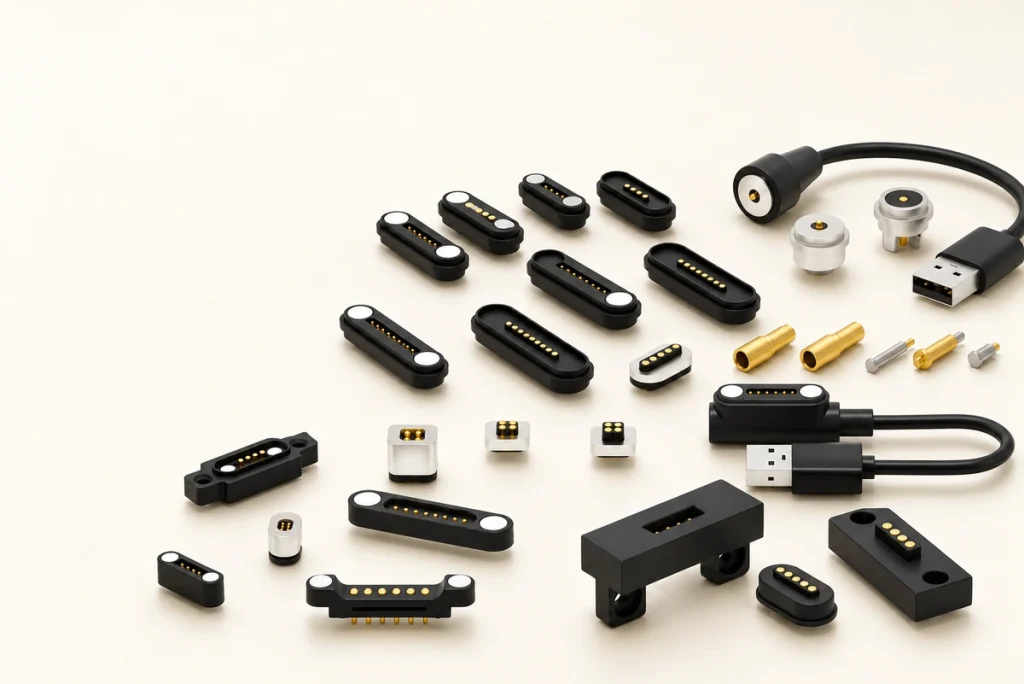
- What a Magnetic Interface Contains
- How Magnetic Mating Works
- Potential Design Benefits
- Care and Maintenance
- What Determines Price?
- Comparing Connector Features
- Procurement and Engineering Checks
- Magnetic Connector Questions
Magnetic interfaces pair magnetic guidance with spring-loaded contacts for convenient power, signal or data connections. This guide covers their operation, contact arrangements, advantages, applications, specifications, sealing, current capability and the requirements used to select a suitable interface.
Magnetic connectorsWhat a Magnetic Interface Contains
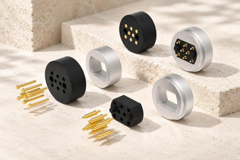
Magnets guide, align and retain the mating parts of a magnetic electrical interface. A typical design combines spring-loaded contacts, magnets and an insulated housing. Charging docks, wearables, medical electronics, handheld devices and modular industrial equipment are possible applications.
Core Definition and Structure
The interface must balance retention, conductivity, mechanical life, electrical insulation and handling. Pogo contacts are useful in many designs because their working travel can accommodate small height differences while maintaining pressure against a mating pad; those variations must remain within the specified travel and tolerance limits.
electrical conductivityThe main components usually include:
Magnets: Provide automatic alignment and holding force.
Pogo pins or contact terminals: Transfer power and/or signal.
Pogo pinsPlastic or metal housing: Locates and protects the assembly, with the insulation structure required by the circuit.
The table summarizes common components and candidate materials, rather than a specification for a particular model.
| Component | Function | Common Material | Why It Matters |
|---|---|---|---|
| Magnet | Alignment and retention | NdFeB magnet | Determines snap-on feel and holding strength |
| Pogo pin | Electrical connection | Brass or copper alloy with gold plating | Improves conductivity and cycle life |
| Housing | Protection and positioning | PA, PBT, LCP, or ABS | Affects durability, heat resistance, and insulation |
| Cable/PCB end | Product integration | Wire, SMT, through-hole, or custom terminal | Determines assembly method |
Scroll horizontally to view every column.
Design note: Define current, contact count, magnetic polarity and available installation space before requesting samples. Review those inputs alongside the complete operating requirements.
How Magnetic Mating Works
Magnetic attraction draws the halves toward their mating position, and conductive pins or pads close the circuit. In a pogo interface, compressed spring contacts maintain pressure on the opposing surface so power or signals can pass with less alignment effort from the user.
Video material pending replacement
Magnetic Alignment and Electrical Contact
The user sees a simple attachment process, but its geometry needs precise design. Attraction guides the approaching half into place; the magnet arrangement can also control orientation, particularly when combined with asymmetric polarity or mechanical keys.
A typical connection process works as follows:
Approach: The plug or cable end moves near the device-side connector.
Magnetic capture: Built-in magnets attract and pull the two halves together.
Self-alignment: The connector settles into the designed position.
Contact compression: The spring pin will compress slightly and make contact with the other end.
Power or signal transfer: Current, data, or control signals pass through the conductive path.
Controlled release: Pulling can separate an appropriately designed pair with less stress on the port; validate the release force and direction for the complete product.
Set spring compression and magnetic retention together. Too little contact force can allow dropouts, while excessive force can increase pad damage or wear. The interface should retain securely yet detach with the intended effort.
These factors illustrate the relationship between mechanical design and electrical behavior.
| Working Factor | Good Design Result | Poor Design Risk |
|---|---|---|
| Magnet polarity | Correct orientation and repeatable docking | Reverse connection or weak attachment |
| Spring force | Stable current transfer | Flickering, charging dropouts, or pad wear |
| Contact plating | Low resistance and long service life | Oxidation and unstable performance |
Scroll horizontally to view every column.
Design note: Include vibration, cable movement and repeated docking in validation. A static bench connection can conceal contact problems that appear when the assembly moves.
Potential Design Benefits
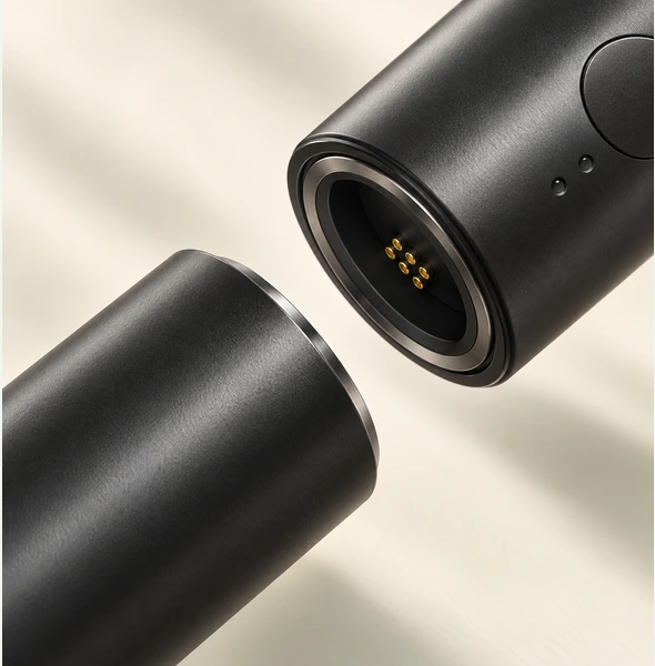
A suitable magnetic interface can simplify docking, speed up attachment, reduce port wear and release during accidental cable pulls. These features can improve handling for frequently charged products, blind mating, compact connection points and designs with sealing requirements; the complete assembly determines the result.
Practical Advantages for Product Design
Reducing the need for forceful plug insertion can support usability and durability. Consumer electronics, wearables, smart home devices, medical equipment and portable industrial tools may benefit, but the design must be compared with an appropriate conventional connector for the same requirements.
Key benefits include:
Convenient attachment: Suitable geometry can support one-handed or blind mating.
Lower port stress: A designed breakaway path can help protect the cable and device during a pull.
Dock integration: Consider charging cradles, handheld scanners, rings, headphones and portable instruments.
Product fit: Customize contact layout, seals, compact housings and industrial design as required.
Repeated mating: A correctly engineered and plated pogo structure can support the required cycling life.
The following benefits are design opportunities, not measured performance guarantees.
| Benefit | User Value | Engineering Value |
|---|---|---|
| Self-alignment | Easier charging and docking | Lower misconnection risk |
| Breakaway safety | Can reduce the risk of a device being pulled off a surface | Reduces port damage |
| Compact size | Better product appearance | Saves PCB and enclosure space |
| Pogo pin contact | Stable Integration | Supports high mating cycles |
| Custom design | Brand-specific user experience | Fits unique mechanical layouts |
Scroll horizontally to view every column.
Design note: Assess lifecycle performance as well as convenience. For daily mating, a reduction in port damage may justify custom development costs, but the product needs evidence to support that cost comparison.
Care and Maintenance
Keep mating surfaces clean, prevent metal debris collecting near the magnets and stay within the current rating. Avoid sharp cable bends and inspect the pogo contacts regularly. Appropriate care supports conductivity, alignment, charging stability and service life.
Cleaning and Service Practices
Do not overlook routine inspection. Magnets can gather small metal particles around the contact face, while dirt, sweat, oil, dust and oxidation can raise resistance or interrupt charging.
Recommended maintenance steps:
Isolate power before cleaning the interface.
Remove visible debris with a manufacturer-approved soft brush, blower or lint-free cloth.
If the manufacturer permits it, gently clean pads with a small amount of electronics-grade isopropyl alcohol. Confirm compatibility with plastics and seals first.
isopropyl alcoholCheck that pogo contacts move freely and return to their original height.
Look for cracking, loose strain relief or wire fatigue at the cable exit.
Limit exposure to metal dust in machining areas and workshops.
Avoid aggressive scraping that can damage the contact finish and shorten its useful life.
Sealed products also need inspection of seals and mating faces. Outdoor and medical devices must follow the complete product’s approved safety, cleaning and hygiene procedures.
Design note: A corrosion-resistant contact finish does not overcome a layer of dirt covering the pins. Contamination can still interrupt the circuit, particularly in demanding environments.
What Determines Price?
Contact count, current capability, magnet strength, plating thickness, seals, housing material, cable complexity and order quantity influence pricing. Standard parts may cost less than custom designs that require tooling, extra tests and certification support; support is distinct from an existing product approval.
Specification and Cost Drivers
A basic low-current two-pin charging interface and a multi-contact sealed interface for medical, industrial or outdoor equipment have different requirements. Custom work can include pin layout, cable length, overmolding, magnet orientation, finish, product marking and packaging. Price the required configuration.
Relative cost categories below are indicative; they do not constitute a quotation.
| Connector Type | Typical Use | Relative Cost Level | Main Cost Drivers |
|---|---|---|---|
| 2-pin magnetic connector | Basic charging | Low | Current rating, cable length, plating |
| 4–6 pin magnetic pogo pin connector | Charging plus signal | Medium | Pin precision, housing design, magnet layout |
| Waterproof magnetic connector | Outdoor and wearable devices | Medium to high | Sealing structure, IP testing, material selection |
| Custom overmolded cable assembly | Consumer electronics | Medium to high | Mold cost, cable spec, strain relief |
| High-current custom connector | Industrial or power products | High | Contact resistance, thermal control, safety testing |
Scroll horizontally to view every column.
The supply form also matters: loose component, PCB-mounted part, cable assembly or complete custom interconnect. Include tooling, validation, assembly work, failure risk and after-sales exposure when comparing total production cost.
Design note: Share target current, voltage, contact functions, drawings and expected annual quantity early. Both electrical requirements and production volume are needed for a meaningful quotation.
Comparing Connector Features
Compare retention force, spring-contact stability, resistance, plating, housing durability, sealing potential and customization. Standard magnetic parts, pogo assemblies and custom solutions may overlap as categories; the actual features and application requirements are the useful basis for selection.
contact resistanceFeature Comparison for Selection
External similarity says little about performance under load, repeated mating, vibration, sweat or outdoor exposure. Review electrical, mechanical and environmental specifications together for the intended application.
The comparison describes broad design options. Qualitative levels and custom targets require confirmation against the actual model and project.
| Feature | Standard Magnetic Connector | Magnetic Pogo Pin Connector | Custom Magtor Solution |
|---|---|---|---|
| Alignment | Good | Very good | Optimized for product structure |
| Contact stability | Moderate to good | High | Tuned by pin force and layout |
| Current capability | Low to medium | Low to high, depending on design | Designed to target rating |
| Signal support | Limited | Better for multi-pin layouts | Custom pin mapping available |
| Waterproof potential | Possible | Strong with proper sealing | IP-focused design support |
| Mating cycle life | Application-dependent | High with quality plating | To be validated against project requirements |
| Industrial design fit | Limited | Flexible | Fully customized appearance |
| Best use case | Simple charging | Charging and signal transfer | Branded, high-volume, or specialized products |
Scroll horizontally to view every column.
A pogo-based magnetic interface can balance convenient mating with consistent contact pressure. Its spring travel accommodates small tolerance variations within the design limits, while magnetic guidance assists docking. Compare that combination with other suitable solutions for the product.
Design note: Evaluate prototypes as well as drawings. Retention feel, docking tolerances and cable exit angles are difficult to assess from specifications alone.
Procurement and Engineering Checks
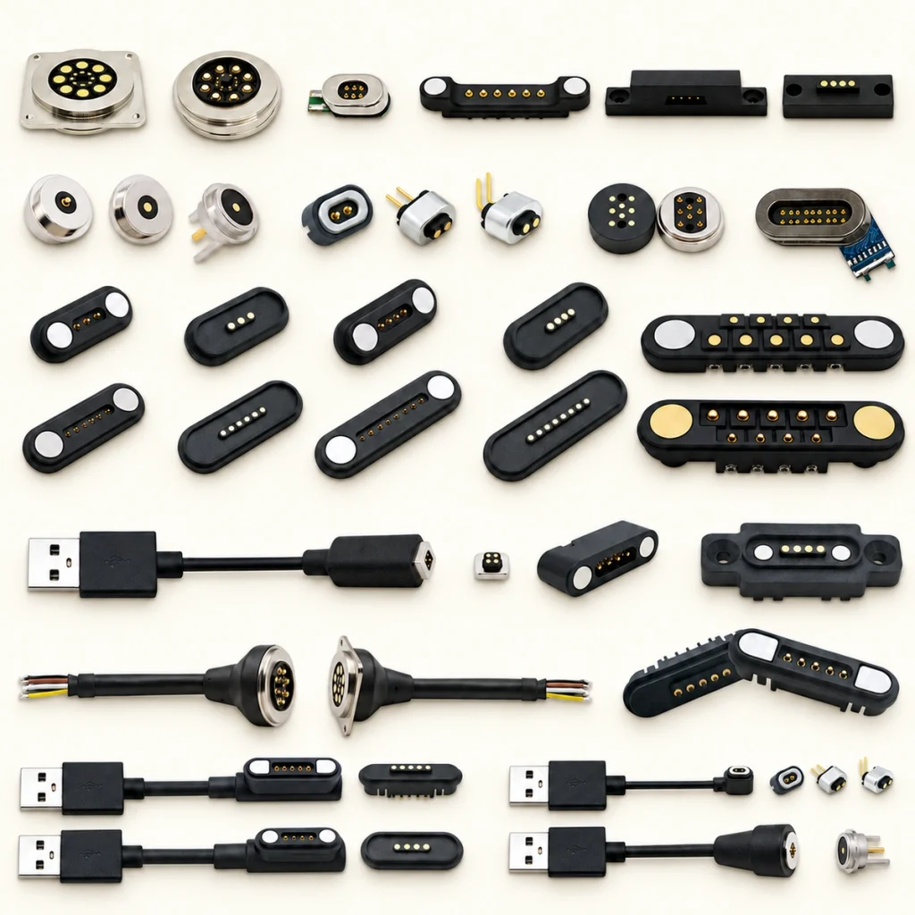
Review electrical rating, fit, cycling requirements, materials, engineering support, customization, lead time, testing and lifecycle cost. A low unit price may offer poor value if it adds assembly difficulty or failure risk.
Buying Checklist for Procurement and Engineering
Engineering, purchasing, quality and product teams should review the selection together. Confirm feasibility, costs and reliability, and keep the supplier involved in custom development: small changes can affect tooling, testing and production yield.
Important buying factors include:
Electrical requirements: Current, voltage, resistance, signal type, and pin assignment.
Mechanical requirements: Size, mounting method, cable direction, mating force, and enclosure space.
Environmental requirements: Waterproof rating, corrosion resistance, temperature range, and cleaning exposure.
Production requirements: MOQ, tooling cost, lead time, assembly method, and packaging.
Quality requirements: Define mating-cycle, salt-spray, current-load and vibration tests, together with appearance inspection.
salt spray testSupplier support: Review engineering resources, relevant custom work, sample turnaround and production consistency.
Use this checklist to agree the evidence required before ordering.
| Buying Factor | Why It Matters | What to Confirm Before Ordering |
|---|---|---|
| Current rating | Supports control of overheating risk | Maximum continuous current and temperature rise |
| Pin count | Defines function capacity | Charging-only or charging plus signal |
| Magnet force | Affects user feel and retention | Pull force, polarity, and docking orientation |
| Plating quality | Affects service life | Gold thickness and corrosion resistance |
| Waterproof design | Protects device reliability | IP rating target and sealing method |
| Custom tooling | Impacts upfront cost | Tooling fee, timeline, and ownership |
| Supplier testing | Reduces production risk | Test reports and inspection standards |
Scroll horizontally to view every column.
Design note: Request samples made with the process planned for volume production. Hand-built prototypes can differ from molded or automated parts, so confirm that the evaluated sample represents the intended process.
Magnetic Connector Questions
Which Requirements Should Guide Selection?
Begin with current, voltage, contact count, available space, mating direction, IP target, retention force and required service life. Establish whether the interface carries charging power, signals or data. Share product drawings, electrical specifications, mounting dimensions and use conditions so a standard or custom solution can be assessed.
How Should Current Capability Be Confirmed?
Current capability depends on contact diameter, material, plating, spring force, the number of power contacts, cable cross-section and heat dissipation. Compact chargers often serve lower currents; high-current designs may use larger contacts or parallel paths. Validate temperature rise and voltage drop under the actual product conditions.
What Determines the Final IP Rating?
Suitable designs can target IP65, IP67 or IP68 using O-rings, adhesive grooves, overmolding, sealed cable exits and protective housings. The final rating belongs to the specified complete assembly. Verify sealing after the connector is installed in its enclosure.
How Can Power and Data Share an Interface?
Separate contacts can route charging power, ground, control, device detection and data. Hybrid layouts may combine larger power contacts with smaller signal contacts. High-speed data also requires evaluation of impedance, shielding, crosstalk, layout and contact stability; contact count alone does not establish protocol performance.
What Determines Mating Life?
Appropriate designs may be developed for thousands or tens of thousands of mating cycles. Actual life depends on contact structure, spring force, gold thickness, alignment, load, contamination and environment. Before volume approval, request relevant cycling, resistance, salt-spray, retention and temperature-rise evidence with its test conditions.
What Information Is Needed for an OEM Design?
Custom work can address shape, dimensions, contact count and pitch, current capability, retention, polarity, mounting, plating, cable assembly and sealing. Provide drawings, available space, electrical needs, cycling targets, environment, estimated quantity and certification requirements for a project proposal.
Choosing for the Application
Magnetic interfaces can suit fast docking, compact products and convenient charging. Understanding their operation, cost drivers and specification differences helps a product team develop the required safety and durability into its selected solution.
Final Selection Guidance
Match the interface to its use conditions. A simple charger may need a standard two-contact part, while a wearable, medical product or industrial handheld may require a custom pogo interface with seals, controlled resistance and validated cycling life.
Before final selection, confirm:
Electrical rating and safety margin.
Pin layout and signal requirements.
Magnet polarity and retention force.
Housing size and installation method.
Waterproof, corrosion, and temperature requirements.
Mating cycle life and reliability testing.
Supplier customization and production capacity.
Magtor supports magnetic interface development for charging, signals, docking and custom device integration. Prepare drawings, target specifications and application details to support a focused engineering evaluation.
MagtorDesign note: Involve the connector supplier while enclosure and PCB layouts are still flexible. Small adjustments can improve alignment, durability, assembly and the way the finished product handles.