
Three-pin Magnetic Connectors: Functions, Design and Selection
Published on July 28, 2026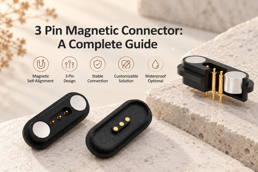
- Understanding a Three-contact Magnetic Interface
- From Magnetic Capture to Electrical Contact
- Common Faults and Their Causes
- Names Used for Three-contact Connectors
- The Wider Magnetic Connector Category
- Features to Compare
- Cost Drivers and Purchase Checks
- Questions About Three-contact Designs
A three-pin magnetic interface uses magnetic guidance and pogo contacts to route power or signals. This guide takes engineers and buyers through contact assignments, current capability, sealing, installation, applications and the requirements that determine a suitable design.
3 pin magnetic connectorUnderstanding a Three-contact Magnetic Interface
A three-pin magnetic connector has three conductive contacts and a magnetic coupling arrangement that helps its mating halves align and attach. Compact electronics commonly use it for power, ground and a signal, or for low-voltage charging and data-related functions; the circuit determines the actual assignment.
electrical interconnect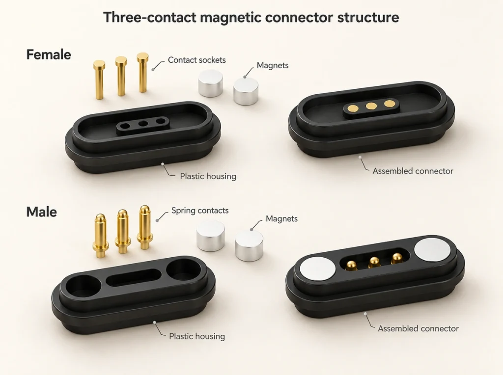
Basic Definition and Contact Layout
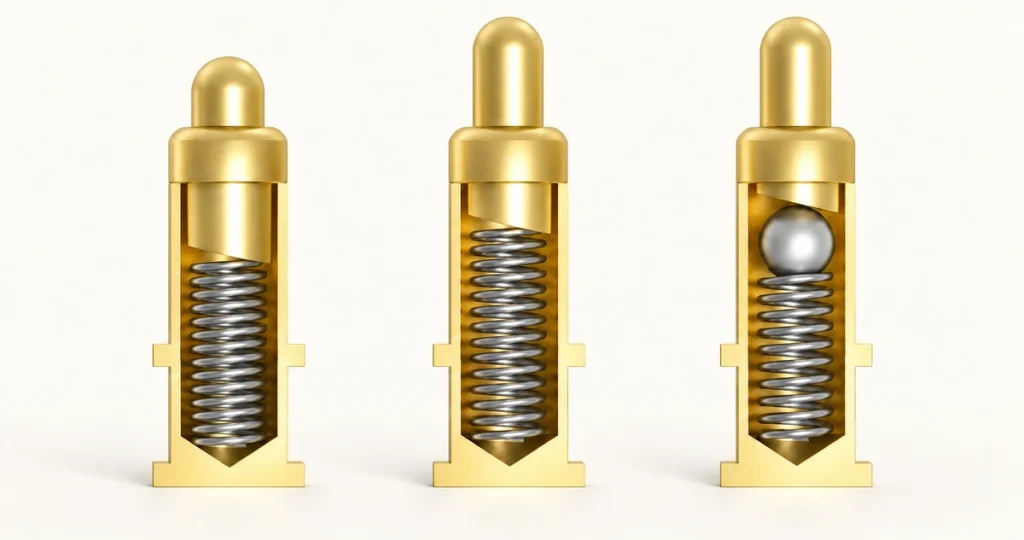
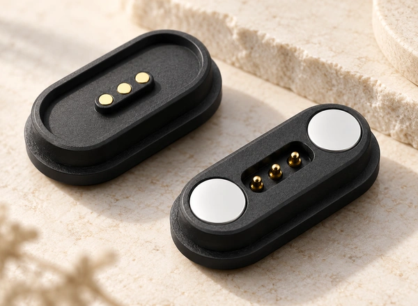
A typical pair has a spring-contact half and a mating-contact half, often described as male and female. The spring contact uses a compressible pin, barrel and spring, while its counterpart commonly presents a copper contact surface. Magnets draw the halves together; correct alignment also depends on their mechanical geometry and polarity.
Possible circuit arrangements include:
Power + Ground + Signal for smart accessories, sensors, and charging docks.
Positive + Negative + Detection Pin for controlled charging interfaces.
Power + Data + Ground for low-speed communication or device identification.
Three separate signal paths for a dedicated equipment interface, with their required reference or isolation defined by the circuit.
The table outlines possible contact roles and the checks each role needs.
| Pin Function | Common Use | Design Consideration |
|---|---|---|
| VCC / Positive | Charging or device power | Requires correct current rating and plating |
| GND / Negative | Return path and shielding reference | Should be stable and low resistance |
| Signal / ID | Data, detection, or control | Needs reliable contact and noise control |
Scroll horizontally to view every column.
Contact count is only the starting point. Check magnetic polarity, contact force, housing material, plating, rated current and mating life together to assess performance in the intended application.
Design note: Agree the contact assignment before ordering samples. Interfaces with the same external shape can have different wiring, polarity and current capability.
From Magnetic Capture to Electrical Contact
Magnets guide and retain the two halves, while three conductive contacts complete the electrical paths. Pogo pins, mating pads or other spring contacts provide the pressure needed for power or signal transfer; the magnets assist alignment rather than replacing the contact system.
Magnetic Alignment and Electrical Contact Process
As the correctly oriented halves approach, magnetic attraction guides them toward the mating position. Housing guidance and contact geometry then bring the three contact points together so their intended electrical paths can conduct.
A typical mating sequence has five stages:
Approach: Bring the cable, dock or module near the interface on the device.
Capture: Magnetic attraction draws the pair closer and can correct a small initial offset.
Seating: The housing constrains rotation and guides each contact toward its intended pad.
Connection: The three paths make contact for the defined power, return and signal functions.
Release: Under an angled cable pull, an appropriately designed magnetic interface can separate more readily than a rigid plug, helping reduce port stress. Release behavior must be validated for the assembly.
Check these design requirements:
Balance magnetic retention against the force needed to remove the connector.
Select a contact finish for the expected corrosion, sweat, oxidation and repeated wear.
Provide suitable spacing and protection against unintended contact between electrical paths.
Validate the assembly under vibration, cable pull and repeated mating.
Design note: A connector that snaps together still needs electrical evaluation. Measure contact resistance during controlled small cable movements; fluctuations can indicate inadequate spring force or an unsuitable mating-pad layout.
contact resistanceCommon Faults and Their Causes
A three-contact interface can suffer intermittent contact, oxidation, loose mating, wiring errors, shorts, weak retention or inadequate current capability. Check specification mismatches, plating, contamination and use outside the intended environment before deciding on a remedy.
short circuits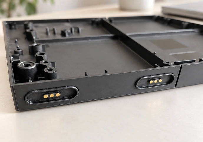
Failure Modes and Troubleshooting Priorities
Convenient mating does not remove the need for careful integration. Exposed or partly exposed contacts can be affected over time by dust, moisture, sweat, metal debris and abrasion.
Use the following symptoms as starting points for diagnosis, rather than confirmed causes.
| Problem | Likely Cause | Practical Fix |
|---|---|---|
| Intermittent charging | Weak contact force or dirty pads | With power isolated, clean by an approved method and check spring travel |
| Connector heats up | Current exceeds rating or contact resistance is high | Check load and contact resistance; review the current rating and plating |
| Wrong device behavior | Pinout mismatch | Confirm wiring map before production |
| Magnetic connection feels weak | Incorrect magnet size, gap, or polarity | Review magnetic force and housing tolerance |
| Short circuit risk | Metal debris or insufficient spacing | Add protection design and improve contact layout |
| Corrosion | Humidity, sweat, or poor plating | Assess a suitable gold finish or sealing where the exposure requires it |
Scroll horizontally to view every column.
Evaluate the combination of load, contact resistance, user handling and environmental exposure. A bench sample can function initially yet fail after thousands of mating cycles if the plating, spring force or housing tolerance is unsuitable.
Design note: Describe sweat, outdoor humidity, vibration, charging current and mating frequency early in the project. These conditions are more useful for selection than external appearance alone.
Names Used for Three-contact Connectors
The same contact count may be described as three-pin, three-pole, three-contact or three-way. When magnets guide and retain the pair, it may be called a three-pin magnetic connector. Structure, industry terminology, mounting and circuit function determine which description is most useful.
Naming Conventions Across Applications
Names may refer to contact count, structure, electrical purpose or mechanical design. A three-contact magnetic interface belongs within the broader three-contact category; three pins alone do not make a connector magnetic.
Common naming examples include:
3-pin pogo pin connector: Uses spring-loaded pins for contact pressure.
3-pole magnetic connector: Describes three conductive poles with magnetic mating.
3-contact charging connector: Used when the main purpose is battery charging.
3-way connector: Often used in wiring or harness terminology.
3-pin dock connector: Used when the connector mounts to a cradle or base station.
Custom magnetic charging interface: Used for proprietary product designs.
These names describe different aspects of an interface; they do not establish interchangeability.
| Name | Typical Meaning | Magnetic? |
|---|---|---|
| 3 pin connector | General three-contact connector | Not necessarily |
| 3 Pin Magnetic Connector | Three contacts with magnetic coupling | Yes |
| 3 pin pogo connector | Spring-loaded three-pin contact system | Sometimes |
| 3 pole connector | Three electrical poles | Not necessarily |
| 3 pin charging connector | Charging-focused three-pin interface | Sometimes |
Scroll horizontally to view every column.
When discussing a design with Magtor, provide drawings, electrical requirements, target current, mounting and the intended product application. A connector name alone rarely defines the required interface.
Design note: Use 2D drawings or 3D models to establish the actual specifications, then evaluate samples against them before finalizing the design.
The Wider Magnetic Connector Category
A magnetic electrical connector uses magnets to assist alignment, attachment and release between mating parts. Its conductive system may use pogo pins, pads, spring contacts or custom terminals, making the category useful for frequent connections where convenient operation and durability matter.
Magnetic Connector Design Principles
Magnetic guidance can simplify mating compared with inserting a conventional plug into a socket. Compact devices, sealed enclosures, wearables and frequently docked products may benefit, provided the complete interface meets the application requirements.
Main elements of a magnetic connector include:
Magnets: Provide attraction, alignment, and retention force.
Contacts: Carry power, signal, or data.
Housing: Controls orientation, spacing, and mechanical protection.
Plating: Improves conductivity and corrosion resistance.
corrosionInsulation: Prevents shorts between adjacent pins.
Mounting structure: Supports PCB, cable, panel, or overmold integration.
PCB
Potential benefits include lower mating wear, easier handling and release during accidental cable pulls. The design must also address reverse mating, attracted metal particles and contact instability during vibration.
Design note: Treat magnetic retention as one part of the interface. Balance it with contact force, housing guidance and electrical protection rather than simply choosing the strongest magnet.
Features to Compare
A three-contact magnetic interface can combine guided mating, three electrical routes, quick attachment, compact packaging and a customizable pin assignment. It may reduce mechanical wear and simplify handling compared with a plug-in interface, but resistance, polarity and environmental protection still need careful control.
Feature Comparison for Product Selection
The comparison is qualitative guidance. Individual connector models, their structure and the intended conditions determine the actual result.
| Feature | 3 Pin Magnetic Connector | Standard 3 Pin Plug | USB-Style Connector | Custom Dock Connector |
|---|---|---|---|---|
| Mating convenience | Very high | Medium | Medium to high | High |
| Self-alignment | Yes | No | Limited | Sometimes |
| Quick release | Yes | No | No | Sometimes |
| Contact wear | Lower when well-designed | Medium | Medium | Depends on structure |
| Pinout flexibility | High | Medium | Low to medium | High |
| Current capacity | Customizable | Varies | Standard-dependent | Customizable |
| Waterproof potential | Good with proper design | Moderate | Requires special design | Good |
| User safety under pull | Strong advantage | Lower | Lower | Medium |
| Tooling customization | Often required | Low to medium | Low | High |
| Best use cases | Wearables, chargers, docks, sensors | General wiring | Consumer electronics | Dedicated equipment |
Scroll horizontally to view every column.
Frequent docking is a useful application for a three-contact magnetic pair. A flatter interface than many socket arrangements can also support a sealed or partly sealed enclosure design, although sealing performance requires separate verification.
Important features to evaluate include:
Rated voltage and current.
Contact resistance and stability.
Magnet retention force.
Mating cycle life.
Operating temperature.
Salt spray, sweat, or humidity resistance.
PCB, cable, or panel mounting method.
Anti-reverse or keyed structure.
Custom cable overmolding options.
Design note: Compare alternatives against a weighted requirements checklist, as well as price. A higher unit cost may be worthwhile if the complete design improves charging reliability, simplifies use or reduces returns; confirm those benefits in the product.
Cost Drivers and Purchase Checks
Contact material, gold thickness, magnet dimensions, housing material, sealing, cable assembly, customization, testing and order volume all influence cost. Assess the cost of the complete application rather than the connector’s unit price alone.
Pricing Drivers and Procurement Checklist
Semi-custom and fully custom designs can have widely different costs. A simple low-current consumer charging interface may be less expensive than a rugged design for medical, industrial or outdoor equipment; obtain a quotation against the actual requirements.
The following cost effects are indicative trends, rather than a price schedule.
| Buying Factor | Cost Impact | Why It Matters |
|---|---|---|
| Gold plating thickness | Medium to high | Improves corrosion resistance and contact life |
| Magnet grade and size | Medium | Affects retention force and alignment |
| Housing material | Medium | Influences durability, insulation, and appearance |
| Waterproof design | High | May require sealing, molding, or special structure |
| Cable assembly | Medium to high | Adds labor, materials, and testing |
| Custom tooling | High upfront | Needed for unique shapes or mounting requirements |
| Electrical testing | Medium | Verifies contact resistance and the required electrical safety performance |
| Order quantity | High | Larger volumes usually reduce unit cost |
Scroll horizontally to view every column.
Recommended buying checklist:
Define current, voltage, and signal requirements.
Confirm pinout and polarity.
Choose mating style: cable-to-device, board-to-board, dock-to-device, or panel mount.
Specify humidity, sweat, dust, vibration and outdoor exposure relevant to the operating environment.
Request drawings, samples, and test data.
Validate connector performance in the final product housing.
Confirm production tolerance and quality inspection standards.
Send Magtor your drawings, product photos, expected cable length, mounting arrangement and target certification requirements. That information supports a more focused engineering review and quotation.
MagtorDesign note: Test samples inside the intended product housing before fixing the design. Small changes in plastic height, magnetic gap or PCB position can change retention feel and contact reliability.
Questions About Three-contact Designs
Where Are Three-contact Magnetic Interfaces Used?
Wearables, medical electronics, smart devices and charging docks commonly use three contacts for power and return plus a signal or detection function. The product circuit determines their roles.
Which Circuit Functions Can Three Contacts Provide?
Depending on the circuit, the contacts can support power, return, signals, charge detection, identification, sensing or low-speed communication. Define the required combination and reference paths before choosing the pinout.
How Is Current Capability Established?
Current capability depends on contact diameter, resistance, materials, plating, spring force and heat dissipation. General guidance cites 1 A to 5 A for some designs and up to 30 A for specially engineered high-current solutions. Those figures are not a universal three-pin rating: confirm the exact model, current path and thermal test conditions.
How Can a Three-contact Interface Meet Sealing Requirements?
A three-contact interface can be engineered for IP65, IP67 or IP68 requirements using suitable sealing, housing geometry and overmolding. The rating must be verified for the complete specified assembly and its test conditions.
What Does a Third Contact Add?
Two contacts commonly provide positive and negative power paths. A third contact creates room for another defined role, such as a signal, detection, sensing or communication function.
Which Design Features Can Be Customized?
Customization can address dimensions, pitch, current capability, retention, mounting, cable length, sealing, plating and housing geometry. Define those requirements for the application before developing the interface.
Selecting the Complete Interface
For products that need frequent mating, a three-contact magnetic interface can offer quick attachment and guided alignment. Evaluate contact functions, retention, electrical design, likely faults and purchasing requirements together to work toward the required safety and durability.
Final Selection Guidance
Selection should reflect the real product environment as well as its drawing. Assess electrical load, mechanical fit, user handling, materials and production consistency as a complete system.
Before final selection, confirm:
The exact pin function and wiring sequence.
Required current and voltage rating.
Contact resistance under movement.
Magnet strength and mating direction.
Plating material and corrosion resistance.
Mounting method and housing tolerance.
Required cable length, overmold, or PCB layout.
Environmental exposure and expected mating cycles.
Sample test results in the final device assembly.
Magtor can support selection, custom development, samples and production review for compact magnetic interfaces intended for durable, convenient operation.
Design note: Start with the application’s current requirement, available space, environment and mating frequency. Use those requirements to choose an existing three-contact design or define a custom one.