
Selecting a Four-contact Magnetic Connector for Your Device
Published on July 17, 2026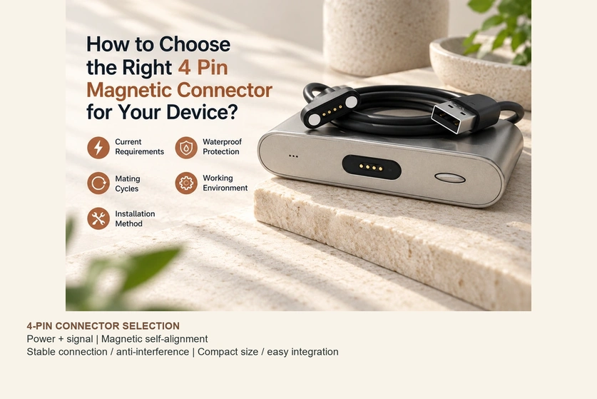
- Start with the Required Current
- Check the Operating Environment
- Specify the Mating Life
- Define the Required Water Protection
- Select a Mounting Method
- Reasons to Consider Four Contacts
- Engineering Selection Checklist
A four-contact magnetic interface should be selected against the device’s electrical, environmental and mechanical requirements. This guide works through current, exposure conditions, mating life, sealing and mounting choices so that the chosen assembly can be evaluated for the intended power and signal functions.
Four-contact magnetic interfaceStart with the Required Current
Establish the required current and duty cycle before choosing contact size or allocating the four paths.
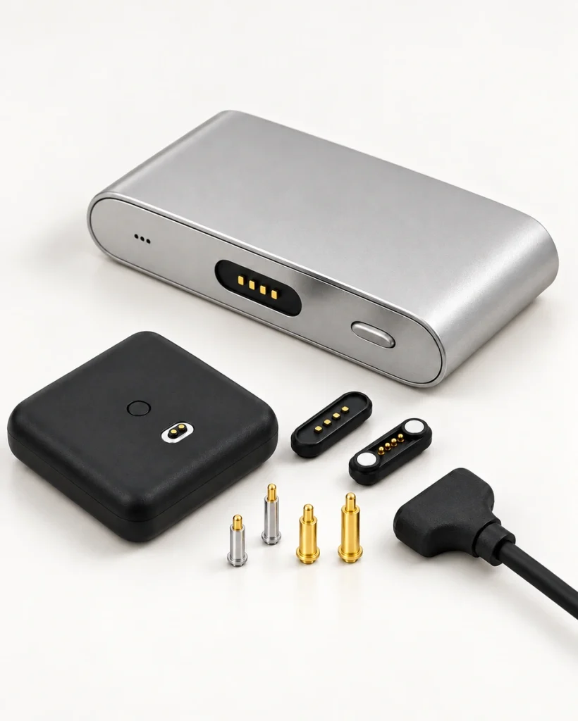
A small wearable and an industrial charger may need very different conductor sizes, contact resistance and thermal performance. Evaluate the full cable, contacts and terminations at the required operating conditions rather than selecting solely by the number of pins.
Lower-current Devices
Examples to evaluate include:
Smart watches.
Fitness trackers.
Small wearable products.
Portable sensors.
A compact four-contact assembly with smaller spring contacts may suit these devices when its documented current and temperature limits meet the actual charging requirement.
Illustrative characteristics for this category are:
Example current range: 0.5–3A per contact, subject to the selected contact’s rating and operating conditions.
A compact assembly.
A small mounting envelope.
Suitability for the device’s lower power demand.
Higher-current Devices
For higher power or faster charging, assess the following design features against measured resistance and temperature rise:
A larger spring-contact diameter where required.
Lower contact resistance.
A suitable gold-plating thickness for the exposure and life target.
A spring structure matched to force and travel requirements.
Multiple power contacts where verified current sharing is needed.
Applications that may require this assessment include:
Smart handheld terminals.
Industrial equipment.
Charging stations.
Battery-powered equipment.
Four contacts can be allocated between power and signals. An example division is:
Pins 1 and 2: power supply and return paths, as defined by the drawing.
Pins 3 and 4: supported data or control-signal paths.
Separating power and signals supports multiple functions, but it does not itself increase current capacity. The power-contact rating, return path and thermal design still determine the allowable load.
Check the Operating Environment
Define the exposure conditions that the connector must withstand throughout its service life.

A configuration intended for a clean indoor space may need different housing, sealing and surface treatments for an outdoor or industrial product. Select these features from the actual exposure profile.
Chemicals, cosmetics, sweat and other contaminants can affect the contact finish. Gold plating is one option, but its durability depends on thickness, substrate, wear and exposure; it does not inevitably fail or guarantee protection. A qualified multilayer or composite coating may be appropriate for a particular environment.
Outdoor, medical, automotive and industrial designs should evaluate contact plating, corrosion-resistant materials and the required salt-spray performance. A suitable process can reduce oxidation and corrosion associated with moisture, sweat and chemicals, while mechanical stability must also be verified after aging and repeated use.
Specify the Mating Life
Set the expected number of connection and disconnection cycles and the approach direction. Insertion-style USB interfaces also have defined durability requirements; wear depends on the specific interface, materials, loading and test method rather than simply its male-and-female construction.
USB interfaceSpring contacts can reduce insertion-related sliding when they mate against pads, although contact pressure, rubbing, contamination and side loading still cause wear. Targets in the tens of thousands or, for some qualified designs, hundreds of thousands of cycles are possible examples—not a universal life rating for four-contact magnetic connectors.
Define the Required Water Protection
Specify water exposure and the protected state of the assembly when moisture or outdoor use is expected.
Potential protection targets for appropriately designed and tested four-contact assemblies include:
IP65.
IP66.
IP67.
IP68.
Considering IP65 and IP66
Match the applicable dust and water-jet requirements to uses such as:
Equipment requiring dust protection.
Products exposed to water within the selected IP65 or IP66 test conditions.
Indoor industrial equipment with the corresponding exposure requirement.
Considering IP67 and IP68
Immersion-related protection may be relevant to the following products, depending on their actual exposure:
Wearable devices.
Outdoor electronics.
Medical equipment.
Smart sports products.
Features to assess in a sealed magnetic assembly include:
A sealed housing structure.
An appropriate gasket arrangement.
Corrosion-resistant contacts.
A molding or encapsulation process suitable for the seal design.
For a wearable exposed to sweat, an IP test alone does not establish resistance to skin oils or corrosion. Specify those exposures separately, and confirm the tested mated or unmated state and any immersion conditions.
Select a Mounting Method
Mounting affects assembly sequence, packaging, service access and the loads transferred to the device.
The following mounting arrangements are available in different four-contact magnetic designs.
PCB-mounted Assembly
Potential integration benefits are:
Direct solder attachment to a PCB using the specified process.
A compact integration envelope.
An assembly method compatible with volume production.
Typical uses to assess include:
Smart devices.
Charging docks.
Consumer electronics.
Cable-connected Assembly
Potential integration benefits are:
More flexibility in locating the interface.
Routing options for complex internal structures.
Typical uses to assess include:
Industrial equipment.
Medical devices.
Portable electronics.
Panel-mounted Assembly
Potential integration benefits are:
Mechanical fixation to a panel or enclosure.
Placement at an external device interface.
Typical uses to assess include:
Control equipment.
Industrial terminals.
Choose the mounting arrangement after reviewing:
Available internal space.
The assembly process.
Required mechanical strength.
Production efficiency and repeatability.
Reasons to Consider Four Contacts
A suitable four-contact magnetic design may provide the following benefits, subject to its construction and verification.
Guided Attachment
The magnetic arrangement can guide the mating parts within its specified capture range, reducing the precision the user needs during attachment.
Managing Misalignment
Magnet polarity and locating features can discourage an incorrect orientation and reduce forced insertion. Verify reverse approach and offset cases; magnetic attraction alone is not a complete error-proofing system.
Compact Packaging
Combining spring contacts and magnets can produce a compact interface where contact spacing, current, insulation and retention requirements permit it. Compare the actual drawings rather than assuming it is smaller than every alternative.
Several Electrical Functions
The four paths may be assigned to supported combinations of:
Charging power.
Data transmission.
Signal communication.
Device control.
This flexibility can suit smart-device designs when the contact allocation and circuitry are defined together.
Engineering Selection Checklist
Use the following checks before committing to a four-contact magnetic assembly.
| Requirement | Design checks |
|---|---|
| Current demand | Contact size, resistance and verified distribution of power paths |
| Operating environment | Corrosion resistance, sealing and temperature range |
| Connection frequency | Specified spring-contact life and plating performance |
| Water-protection requirement | Required IP test conditions and sealing structure |
| Mounting method | PCB, cable or panel integration |
| Space constraint | Assembly dimensions and the magnetic locating arrangement |
| Signal functions | Contact allocation and the implemented electrical interface |
Scroll horizontally to view every column.
Selection Summary
Balance electrical performance, exposure protection, mechanical life and mounting requirements. Document current and duty cycle, operating conditions, expected connection cycles and the required seal state, then validate the selected assembly in the device rather than relying on generic connector descriptions.
For a compact charging or combined-function interface, discuss a four-contact magnetic assembly with Magtor. Provide the electrical assignment, mechanical envelope and operating conditions so that the spring-contact design can be assessed for your product.
Magtor