
Two-contact Magnetic Connectors: Current and Performance
Published on July 14, 2026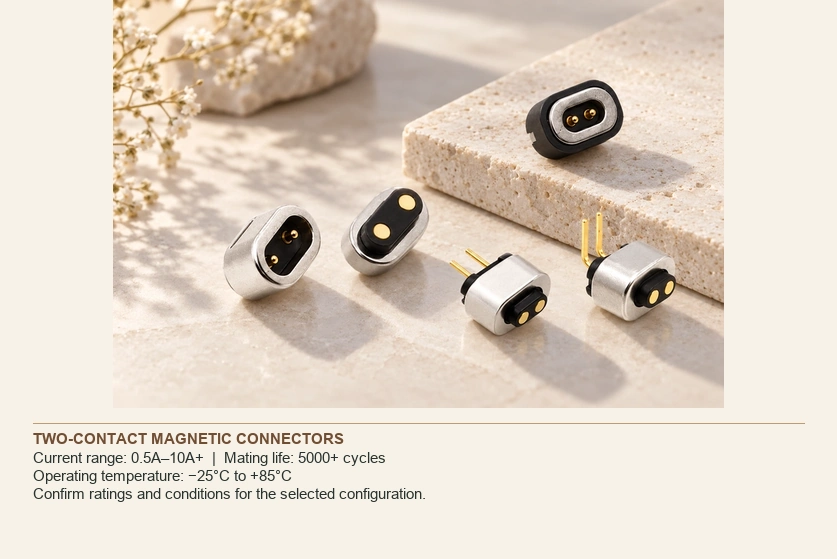
- Interpreting the Current Rating
- Contact Factors Behind Current Capacity
- Thermal Behavior in the Device
- Magnetic Retention and Engagement
- Contact Materials and Coatings
- Mating Life and Validation
- Exposure and Sealing Requirements
- A Selection Checklist
- Application Examples
Selecting a two-contact magnetic interface means checking more than its advertised amperage. Contact resistance, temperature rise, retention, mating life and environmental protection determine whether it fits the actual product. This guide connects those performance factors to the requirements of wearables, smart electronics and industrial assemblies.
two-contact magnetic connectorInterpreting the Current Rating
A continuous-current rating applies under defined conditions and acceptance limits, including permitted temperature rise. A peak rating is different. Obtain the selected connector’s test conditions and operating limits before applying either value.
Illustrative design categories include:
| Design example | Current range to verify | Application examples |
|---|---|---|
| Miniature two-contact magnetic interface | 0.5A–1.5A | Suitable wearables, medical devices and sensors |
| Standard two-contact magnetic interface | 1A–3A | Smart devices and charging equipment |
| Higher-current two-contact magnetic interface | 3A–10A+ | Suitable power tools and industrial electronics |
Scroll horizontally to view every column.
A small wearable may need a lower charging load than a smart-home or industrial product. Use the actual electrical requirement rather than choosing a category from appearance alone.
Match the operating and transient load to a verified rating with appropriate conditions, instead of selecting only the highest advertised number.
Contact Factors Behind Current Capacity
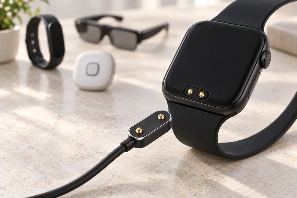
Several design parameters affect the permissible load of a two-contact interface.
Contact Resistance
Resistance is a key part of both loaded voltage drop and connector heating.
A suitably low-resistance path can help achieve:
Limited voltage loss.
Temperature rise within the requirement.
The required charging power-transfer performance.
Operating conditions compatible with the intended contact life.
For a pogo-contact assembly, review:
magnetic connectorsMating-surface condition.
The coating system.
Spring and contact geometry.
Contact pressure.
Manufacturing dimensions and control.
Gold is one coating option for stable mating resistance and corrosion exposure. Its suitability depends on the complete stack, thickness, wear and contact materials, not a gold-plated label alone.
Spring-contact Structure
A pogo arrangement uses compression and spring return to establish engagement through the specified travel. That mechanism must suit the mounting and electrical paths.
Its design influences:
Current-carrying performance.
Mechanical engagement.
Contact stability.
Important parameters include force and contact dimensions:
Spring Force
The spring should supply the required pressure between the mating surfaces throughout the intended working travel.
Insufficient pressure can contribute to:
Intermittent charging.
Signal interruption where a signal is assigned.
Higher contact resistance.
Excessive force can increase:
Mechanical wear.
Contact or mounting damage.
The effort required to engage the assembly.
Contact Diameter
A larger conductive structure may support:
A higher validated current.
A lower-resistance path.
An improved thermal path, depending on the assembly.
Larger contacts also occupy more space. Balance those electrical goals with the available footprint and housing requirements, then verify the actual performance.
Thermal Behavior in the Device
Resistance in the contacts and terminations generates heat while current flows.
Increasing current makes the thermal review more demanding, so temperature rise needs to be checked at the relevant continuous and transient loads.
Evaluate:
Temperature rise at the specified load.
The housing material’s permitted temperature.
PCB and termination heat-dissipation paths.
The actual ambient temperature.
A higher-current design may require:
Larger contacts.
A revised conductive-metal structure.
Suitable power and return routing.
Improved thermal paths.
Room-temperature testing in open air may not represent a sealed device or a hot installation. Validate the connector in thermal conditions relevant to the finished product.
Magnetic Retention and Engagement
The magnetic arrangement guides mating and retains the structure, which affects whether the spring contacts remain properly engaged.
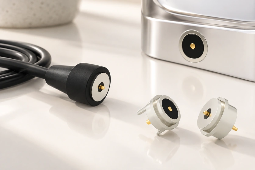
Review the following functions in the assembly:
Guided Alignment
Magnets and locating geometry should guide the intended mating faces and limit incorrect positioning.
Retaining Contact Engagement
The magnets hold the seated assembly while springs provide contact pressure. Confirm the balance of retention and spring force across tolerances.
User Handling
Guidance can simplify attachment within the specified approach range; the final positioning still needs an appropriate locating structure.
Too little retention can permit accidental separation, while too much can make release difficult or increase loads on the device. Test holding and release behavior in the actual portable assembly.
Contact Materials and Coatings
Choose materials for their electrical, mechanical and environmental roles in the interface.
Options mentioned in this discussion include:
Copper alloys.
Brass.
Stainless-steel components where their structural or exposure role is appropriate.
A suitable gold-coating system may help provide:
Stable surface conduction.
Resistance to oxidation at the mating surface.
Performance under the specified corrosion exposure.
Contact resistance maintained over the validated life.
Moisture, sweat and outdoor contaminants make the material and coating review particularly important.
Application examples include:
Smart wearables.
Medical devices.
Outdoor electronics.
Specify the coating and environmental tests for those conditions. A composite coating may be useful for severe corrosion exposure, but the full stack and contact wear need validation.
Mating Life and Validation
A two-contact magnetic design may be developed for frequent mating, with its actual life established by the assembly and conditions.
Wear-related loads to review include:
Misalignment.
Forced engagement.
Other mechanical stress.
Magnetic guidance can limit some of these loads, but cannot eliminate all contact movement or wear.
Relevant checks may include:
Repeated attachment and release.
- Salt-spray exposure where required.
High- and low-temperature performance.
- Vibration testing.
Contact-resistance measurements.
For a wearable or smart accessory charged often, define mating frequency and required service life, then request a matching cycle test.
Exposure and Sealing Requirements
Electronic products may expose a charging interface to conditions beyond a clean indoor mating test.
The two-contact arrangement may need protection against:
Water.
Dust.
Sweat-related corrosion.
Temperature changes.
Relevant application examples include:
Smartwatches.
Fitness trackers.
Medical wearables.
Smart-home products.
Industrial handheld equipment.
For a sealed interface, review:
The sealing arrangement.
Housing and mounting design.
The required IP protection and test state.
Corrosion performance over the intended exposure.
A Selection Checklist
Document these requirement groups before choosing the connector:
Electrical Requirements
Operating voltage; continuous current; peak current and duration; allowed contact resistance; and the required charging behavior.
Mechanical Requirements
Available dimensions; holding and release force; mating-life target; and the installation method.
Environmental Requirements
Water protection and test state; operating temperature; chemical compatibility; and vibration requirements.
Manufacturing Requirements
Required custom-design capability; prototype availability; production consistency; and relevant quality-testing support.
Application Examples
A compact, appropriately validated power interface may suit categories such as:
Smart Wearables
Examples:
Smartwatches.
Fitness trackers.
Health-monitoring devices.
Potential integration goals:
Compact installed size.
Convenient charging attachment.
Stable engagement under the required conditions.
Smart-home Electronics
Examples:
Smart coffee cups.
Smart lighting.
Portable appliances.
Potential integration goals:
Convenient charger attachment.
Straightforward everyday use.
Space-conscious integration.
Medical and Industrial Devices
Examples:
Portable medical equipment with relevant qualification.
Industrial handheld terminals.
Potential integration goals:
Loaded power performance within the specification.
Maintenance access compatible with the required procedure.
The defined durability and exposure performance.
Conclusion
Review current rating together with resistance, temperature rise, magnetic retention and environmental performance. Those factors determine whether the two-contact interface fits the real charging application.
For a compact device, the best-matched candidate is the one that meets electrical, mechanical and product requirements together, rather than simply having the highest current label.
Use that balanced specification to select and validate the assembly. Improvements in charging performance, life or user handling should follow the actual design evidence and product tests.