
30A Magnetic Power Interfaces: Design Requirements
Published on July 10, 2026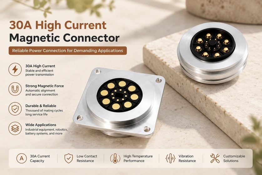
- What a 30A Magnetic Interface Means
- Designing the 30A Current Path
- Potential Integration Benefits
- Power-application Examples
- Evaluating a Manufacturer
Higher-power equipment needs a connector whose current path and thermal behavior match the load. A magnetic interface intended for 30A combines guidance and retention with an appropriately designed contact system. This guide covers that design approach for industrial, robotic and battery applications, with the conditions required to substantiate the rating.
What a 30A Magnetic Interface Means
A 30A magnetic interface is designed for current up to 30 amperes under its specified conditions. Magnetic force assists alignment and retention, while conductive contacts carry power. Confirm whether the rating is continuous or transient, and obtain its voltage, temperature and duty-cycle limits.
high-current magnetic connector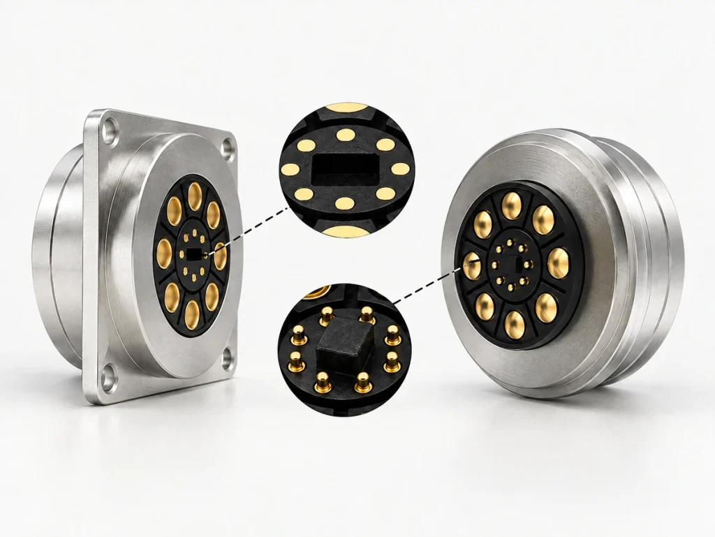
The magnets draw the intended halves toward engagement, and locating features set their final position. Spring-loaded contacts then compress to establish power and any separately assigned signal paths. This avoids conventional plug insertion without removing the need to verify orientation and contact loading.
Possible components of the arrangement include:
High-current pogo contacts — a larger conductive structure designed and tested for the required load.
A mix of larger power contacts and smaller signal contacts — using contact size where needed can support a cost-conscious layout, subject to the actual design.
Permanent magnets — guidance and holding force matched to the operating loads.
Permanent magnetsA metal housing or other locating structure — mechanical support appropriate to the assembly.
Insulation — spacing and materials selected for the operating voltage and required protection against shorts.
A coordinated magnetic and contact design can provide convenient attachment within the available space. Stable electrical performance must be verified in the complete assembly.
Designing the 30A Current Path
A compact interface intended for 30A needs a reviewed conductive path, material system and thermal arrangement. Its size alone does not establish that capacity.
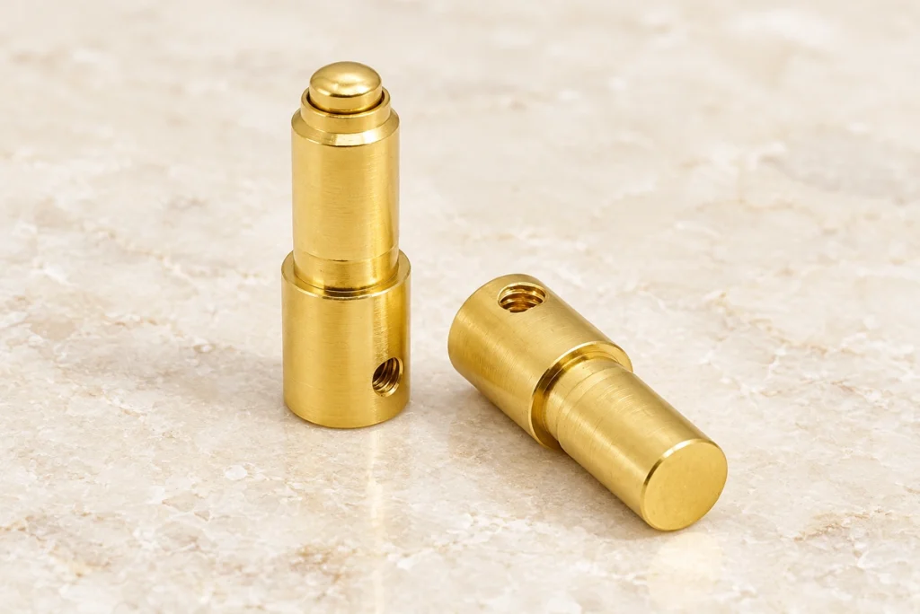
High-current Contact Structure
Compared with a smaller signal contact, a power-contact design may use:
A larger contact diameter.
A suitable conductive material.
Spring force matched to the working travel and contact surface.
A low-resistance mating and termination path.
These features can help control voltage drop and heat generation. Verify the actual resistance and temperature rise at the intended load.
Contact Resistance
Mating resistance affects heating and loaded performance. Design measures to review include:
An appropriate gold-plating system.
Controlled machining and dimensions.
Contact pressure within the specified range.
Check whether those features maintain performance through the required mating-life test, rather than assuming the initial resistance remains unchanged.
Thermal Paths
The thermal design should review:
Contact layout.
Conductive-material selection.
The internal assembly structure.
Current distribution between the defined paths.
Validate temperature under the actual installation, ambient conditions and continuous or peak load. This establishes the permitted operating conditions and overheating margin.
Potential Integration Benefits
A Contact System for the Required Power
A suitably validated 30A interface can serve a higher-current product while fitting its specified space. The useful size and current combination depends on the complete design.
Compared with an undersized candidate connection, the intended goals include:
Current capacity matching the load.
Stable electrical engagement.
Voltage drop within the required limit.
Power transfer that meets the product specification.
For continuous power service, the selected model must specifically support the continuous load and thermal conditions. A 30A label by itself does not establish that operating mode.
Guided Attachment
Magnetic guidance can simplify connection in the intended orientation. Check the polarity and locating geometry; not every magnetic layout allows mating without considering direction.
Potential handling benefits include:
Alignment assistance.
Blind mating within the permitted approach range.
A simpler attachment process.
An operation suited to the intended users.
These features may be useful for equipment with frequent charging or maintenance connections.
Repeated-mating Performance
A face-contact arrangement avoids some insertion friction and related mechanical loads. Its contacts and coating still experience movement and need validation for the intended life.
Possible life-related goals include:
Tens of thousands of mating cycles for a suitable validated assembly.
Limited pull- or insertion-related damage.
Contact resistance maintained within the required limits.
A design meeting its life requirements can reduce servicing, but actual maintenance-cost savings need evidence from the product and operating conditions.
Performance During Movement
Mobile and industrial equipment may need contact stability while its mounting is moving or vibrating.
Validate magnetic retention and electrical continuity during:
Expected equipment movement.
The required vibration profile.
Repeated operating cycles.
A 30A design may suit robotics, automation or portable industrial equipment only when those mechanical requirements and the electrical load are met together.
Power-application Examples
Industrial Equipment
Some industrial products need higher-current interfaces with convenient access for servicing.
Application examples include:
Industrial-control equipment.
Automated machinery.
Industrial handheld terminals.
Test equipment.
A suitable magnetic interface can simplify attachment while meeting the actual loaded power-transfer requirements.
Magnetic connectorsRobotics and Automation
Robot and automation interfaces need to account for operating movement, vibration and alignment.
A validated 30A design may be considered for:
Robot charging interfaces.
AGV power connections.
Robotic modules.
Automated inspection equipment.
Guided mating can help docking operations when the locating structure and control system support the required approach.
Battery and Charging Systems
Battery equipment needs a current path and protection arrangement suited to both normal and transient loads.
Application examples include:
Battery-charging stations.
Portable energy equipment.
Power-management systems.
Energy-storage equipment.
Magnetic guidance may reduce misalignment-related damage, while polarity, exposed-contact protection and loaded engagement still require design validation.
Medical and Smart Equipment
A medical or smart product may need a compact power interface, but its actual load and qualification determine whether a 30A design is relevant.
Application examples include:
Medical instruments.
Beauty equipment.
Smart devices.
Portable electronic systems.
An accessible contact face may help inspection and maintenance. Verify compatibility with the required cleaning process and application qualification instead of assuming that the interface is hygienic or medically approved.
Evaluating a Manufacturer
Supplier capability affects whether the required design can be developed, validated and produced consistently.
Review these areas during supplier selection:
Custom-design Support
Ask which project-specific changes the manufacturer can support, including:
Contact count.
Magnetic holding and release force.
Dimensions.
A suitable sealing design.
OEM or ODM development support.
Electrical and Reliability Testing
Request reports for the relevant configuration and conditions, including:
Loaded-current testing.
Contact-resistance measurements.
Temperature-rise testing.
Salt-spray exposure where required.
Mating-life and durability testing.
The reports should show whether the assembly meets the defined demanding conditions; the existence of a test process alone does not prove every application requirement.
Manufacturing Controls
Assess the controls used for:
Material grades.
Machining dimensions.
Coating processes.
Quality inspection.
Relevant controls and traceability help maintain the agreed configuration in volume production. Verify them for the actual supplier and ordered part.
Conclusion
A magnetic interface intended for 30A can combine convenient attachment with a power-contact system suited to the specified load. Alignment, resistance, temperature rise and mating life need to be validated together. Keep continuous and transient ratings distinct so the claimed capacity matches the actual product’s operating conditions.
Magtor can discuss a 30A magnetic design for industrial equipment, robots, battery systems or other suitable devices. Provide the current profile, voltage, mounting and exposure requirements so the proposed standard or custom assembly can be reviewed and tested against a concrete specification.
Magtor