
Three-contact Magnetic Interfaces: Practical Benefits and Limits
Published on July 7, 2026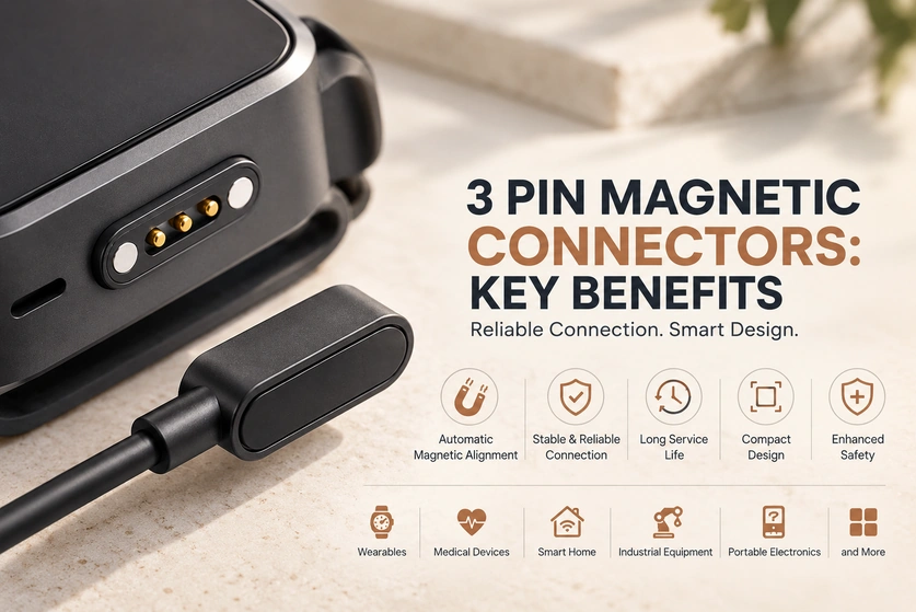
- Magnetic Guidance During Attachment
- Power and an Implemented Signal Path
- Repeated-mating Design
- Controlled Release Under Pull Loads
- A Compact Contact Arrangement
- Customization Inputs
- Sealing and Environmental Protection
- Application Examples
A three-contact magnetic interface combines magnetic guidance with a conductive contact arrangement. It may provide a compact supply, return and signal connection where the circuits and load suit that allocation. This guide reviews potential handling, life and integration benefits, with the validation conditions needed before applying them to a product.
Three-contact magnetic connectorMagnetic Guidance During Attachment
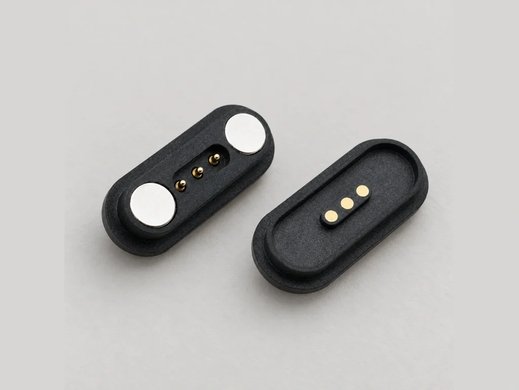
Magnets can guide the mating faces toward the intended position, making attachment quick. The arrangement still has an orientation and an acceptable approach range; verify keying and polarity rather than assuming the user never needs to consider direction.
Guided attachment may be useful in products connected frequently, including:
Smart wearables.
Portable electronics.
Charging docks.
Industrial handheld equipment.
Assess the connection procedure in the actual device to confirm whether guidance makes it easier for the intended users.
Power and an Implemented Signal Path

Spring-loaded pogo contacts can maintain pressure while accommodating the specified height and alignment tolerances. Stable electrical engagement depends on their working travel, contact surface and support in the assembled interface.
Depending on the contact assignment and circuitry, possible functions include:
Charging power.
A compatible data function.
A signal or control path.
A ground or return connection.
Validate contact resistance and continuity under the specified motion, vibration and repeated-mating conditions. Those tests establish whether the design limits interruptions; spring loading alone does not prove reliability.
Repeated-mating Design
A magnetic face-contact arrangement avoids inserting a plug into a socket, which can reduce some insertion-related mechanical loads. Its contact surfaces still move and wear during engagement, so compare the actual life tests with the required use.
USBSuitable three-contact designs may target thousands of cycles. Confirm the exact mating-life evidence and allowed resistance or force change for a product needing long-term service.
Application examples include:
Smartwatches.
Smart glasses.
Beauty devices.
Medical equipment.
Portable instruments.
Controlled Release Under Pull Loads
The detachable arrangement can be designed with a release response for specified cable pulls.
When validated for the intended force and direction, magnetic release may limit loads that contribute to:
Connector damage.
Broken cables.
Pull-related device falls.
Evaluate release behavior in the complete consumer or moving-equipment arrangement. It does not guarantee prevention of every drop or establish product safety by itself.
A Compact Contact Arrangement
Three paths may provide a useful balance between interface area and a simple power-and-signal allocation. Compared with an otherwise similar larger array, fewer contacts can reduce space, but the current rating, spacing and mounting requirements determine the actual dimensions.
A compact arrangement may be useful for:
Wearable electronics.
Miniature smart products.
Portable medical equipment.
IoT devices.
Check the footprint and support geometry when integrating the interface into a thinner enclosure.
Customization Inputs
Possible parameters to discuss with the manufacturer include:
Housing shape, including round, oval or another specified form.
Magnetic holding and release force.
Contact arrangement.
Verified current capacity.
The required sealing structure.
Cable length and construction.
Select materials, the contact-coating system and mechanical support for the actual environmental requirements, then validate the customized assembly.
Sealing and Environmental Protection
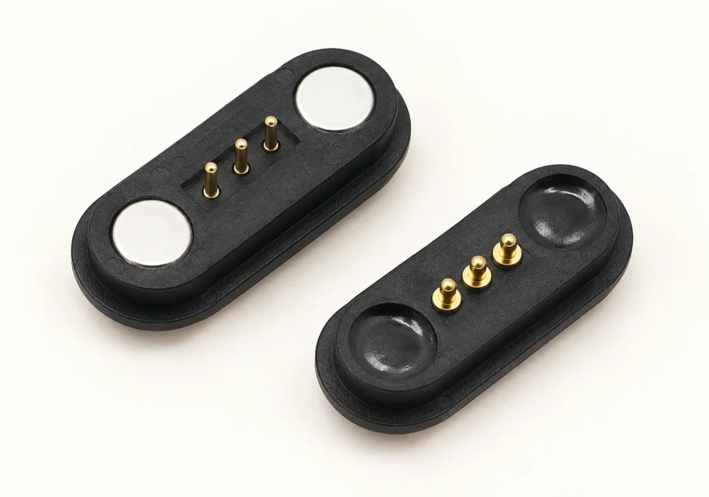
A face-contact interface can be integrated without a conventional insertion opening, providing another approach to enclosure sealing. Exposed contacts and their mounting still need the required protection and contamination review.
magnetic connectorA suitable custom structure may target IP65, IP67 or higher protection. Confirm the protected parts, assembly state and test conditions before selecting it for an outdoor or industrial product.
IP65 and IP67Application Examples
Consider the interface against the actual requirements of application categories such as:
| Application category | Potential design benefit to validate |
|---|---|
| Smart wearables | Compact integration and convenient charging |
| Smart-home products | Straightforward assembly and stable engagement |
| Educational kits | Simple connection, with complete child-product safety qualification |
| Medical devices | Stable contact and compatibility with the required hygiene process |
| Industrial equipment | The required life and vibration performance |
| Portable electronics | Quick attachment and suitable installed size |
Scroll horizontally to view every column.
Conclusion
A three-contact magnetic arrangement can offer guided attachment, compliant contacts and compact integration. Its useful life and performance depend on the actual pinout, materials, mounting and exposure. Engineers should specify and test these together before relying on the potential usability and durability benefits.
For a wearable, smart device or industrial project, discuss the electrical functions and integration limits with Magtor. A standard or custom three-contact interface may be suitable where those requirements fit the structure; the final design needs its own technical evidence and validation plan.
Magtor