
Two-contact Magnetic Charging for Wearables: Benefits and Limits
Published on July 2, 2026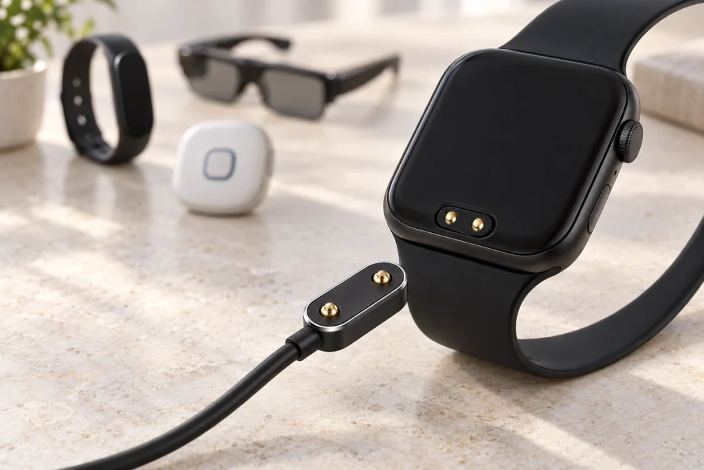
- Why Consider Two-contact Charging for Wearables?
- Operating Principle of a Pogo-contact Interface
- Five Wearable Integration Considerations
- Comparing Charging Interface Options
- Possible Development Priorities
A two-contact magnetic interface may suit a compact wearable that needs a power-only charging connection. Magnetic guidance, device-side contact placement and an appropriate sealing design can support convenient use. This guide reviews the potential benefits and limitations alongside electrical, mechanical and production requirements.
two-contact magnetic connectorWhy Consider Two-contact Charging for Wearables?
Two-contact charging is worth evaluating where a wearable needs only supply and return paths. Compare it against the device’s size, exposure, cost and communication requirements; an unsupported market-share claim is not a basis for choosing the interface.
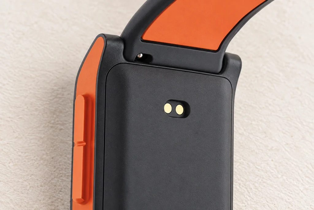
Wearable integration can involve a thin enclosure, little PCB space and a sealing target such as IP67 or IP68. Production cost may also be important. A two-contact magnetic face is one way to address these requirements, but verify the geometry, protected assembly state and manufacturing process rather than assuming a perfect fit for every device.
USB-COperating Principle of a Pogo-contact Interface
One common arrangement uses fixed contact pads on the wearable and a cable-side magnetic head containing pogo contacts. It is an example layout, not a required placement of spring contacts in every product.
The charging-only example assigns two gold-plated contact paths to VCC and GND. It has no separate data contacts in that basic allocation.
Embedded neodymium magnets may guide mating as the head approaches. The source design example gives a 2–4mm capture distance; actual distance depends on magnet grade, geometry and the assembly, so verify it for the selected design.
Within their working travel, pogo springs maintain the specified contact pressure and can accommodate permitted small movements during charging. Check resistance and engagement under the actual load and motion.
An asymmetric magnet arrangement may reject reverse mating. Verify that geometry together with electrical protection; it cannot be assumed to eliminate every short-circuit or polarity risk.
Five Wearable Integration Considerations
Compact Geometry and Available Space
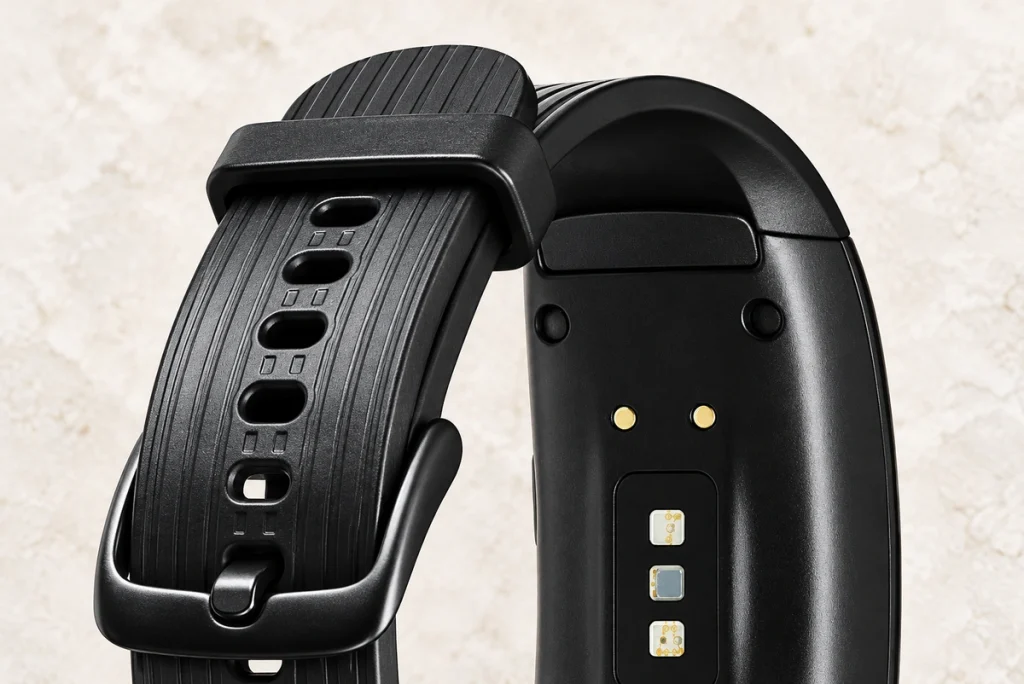
Space is a major constraint in wearable hardware. The source example describes smart-band thicknesses of 8–12mm, while a small smart ring has an even tighter envelope. Use the dimensions of the actual device rather than treating these examples as category-wide specifications.
The contact-face example occupies 10–15mm², with a flat interface rather than a protruding insertion-port housing. Confirm the real PCB, housing and mounting envelope, which may be larger than the contact face itself.
A USB-C receptacle needs a defined internal cavity and mounting structure. A flat rear contact layout may leave more space for a battery, heart-rate sensor or motion circuitry, depending on the complete enclosure design.
A two-contact magnetic design can be an option for very small products such as sleep-monitoring rings or hearing-assistance wearables. It is not the only possible wired interface, and any special application requires its own design review.
Guided Attachment and User Handling
Charging in low light or while traveling can make a small plug awkward to align. Magnetic guidance may simplify that task, but the design still has an intended approach range and orientation that users must be able to achieve.
One-handed attachment — magnets can guide a correctly oriented head toward the device, reducing the alignment effort within the designed range.
Retention during charging — an appropriate holding force can resist a light cable pull, while the actual retention and release thresholds need validation.
Accessible operation — children or older users may find guided attachment helpful, but usability and reductions in charging complaints need real product evaluation.
Sealing the Wearable Enclosure
Fitness and outdoor wearables may specify IP67 or IP68 for an identified exposure and product state. Either an insertion port or face-contact arrangement needs a suitable sealing design and validation; the interface type alone does not prove protection for swimming.
USB, Lightning and clip-based interfaces each need an appropriate enclosure and sealing arrangement. Some designs use covers or plugs, whose service condition must be checked; a cover is not required for every sealed insertion connector.
A two-contact layout may expose only two fixed pads in an otherwise closed rear enclosure. Sealing around those pads can reduce the need for movable covers, but the actual construction must prevent the specified ingress.
Sweat, rain and pool water place different chemical and ingress demands on the assembly. Check sealing and the plated contact system separately, rather than assuming that no water can enter or that gold alone proves salt-spray resistance.
Mechanical Life and Release Behavior
Repeated charging connections can wear a wearable interface. Magnetic face contacts avoid some insertion friction but still need appropriate travel, alignment and wear validation.
A suitable pogo-contact design may target more than 10,000 charging cycles. For comparison, the USB Type-C specification requires a minimum 10,000-cycle durability rating; compare selected assemblies and test conditions rather than applying a blanket 3,000–5,000-cycle claim to USB.
Magnetic guidance reduces the need to push a plug into a port, but the contacts still move and may abrade their mating faces during engagement.
A designed magnetic release can limit cable-pull loads on the device. Verify its threshold and direction together with mounting and circuit protection; it is not an automatic guarantee against internal damage.
Volume Production and Assembly Cost
Cost control can be important in volume wearables, including a fitness band with a target retail price below $50. Interface selection still needs to meet the required performance and manufacturing quality.
A two-path arrangement uses fewer contact parts than a comparable four- or six-contact interface, which may reduce material and assembly complexity. Magnet size and final cost still depend on the design.
Where the contact termination and footprint are suitable, SMT assembly may automate parts of production. Fixed rear pads are not automatically compatible with every placement process; verify the actual mounting and manufacturing route.
Comparing Charging Interface Options
| Comparison point | Two-contact magnetic charging example | USB-C interface to evaluate |
|---|---|---|
| Internal space | A flat contact face can be compact; verify the complete envelope | Requires the specified receptacle and mounting cavity |
| Water protection | Can support an IP68 target with a tested sealing structure and state | Depends on the receptacle and enclosure sealing; a cover is not universally required |
| Mating life | 10,000+ as a design-specific target | USB Type-C specifies at least 10,000 durability cycles; verify the selected assembly |
| User operation | Guided magnetic attachment within the designed approach range | Reversible plug insertion into the receptacle |
| Manufacturing cost | May be cost-conscious for a suitable volume design | Compare actual tooling and assembly cost |
| Additional functions | Supply and return only in this basic charging allocation | Power and data functions depend on the device, cable and implementation |
Scroll horizontally to view every column.
Two Contacts Compared with Four Contacts
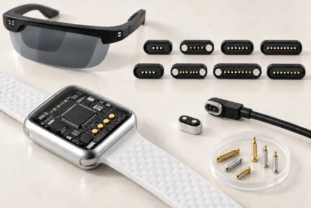
Four contacts offer additional paths that may serve data, identification or other communication functions. Firmware updates and synchronization require a matching circuit and protocol implementation; the contact count does not provide those functions by itself.
four-contact magnetic connectorsPotential two-contact benefit — fewer parts and paths can simplify size, cost and circuit integration.
Two-contact limitation — the supply-and-return allocation has no separate data paths in addition to charging.
Application choice — a fitness band or child’s watch may use two contacts, while another watch may need four for its implemented functions; product tier alone does not dictate that choice.
Two Contacts Compared with Inductive Charging
An inductive charging design adds a coil arrangement and has its own space, efficiency and thermal requirements. Compare measured system performance rather than assuming every wireless design is larger, hotter or less efficient than every contact interface.
A suitable wired contact design may carry 1–2A in this example. Charging speed and heating depend on voltage, control circuitry, resistance and battery limits, not the current value alone.
An inductive system can add components and BOM cost; whether it suits a lower-cost wearable depends on actual quotations and integration requirements.
A wired contact path avoids inductive coil-offset losses, while requiring adequate alignment and contact quality of its own.
Possible Development Priorities
Smaller two-contact interfaces — the source example mentions a 2.0mm magnet pitch for very small wearable or sensor concepts. Any implantable application needs separate biocompatibility and medical-device qualification; a consumer contact design cannot be assumed suitable.
A compact contact system targeting 2A — validate temperature rise and the complete charging design rather than describing current alone as fast charging.
Coatings designed for a 48-hour salt-spray target — specify the test conditions and acceptance limits for outdoor or marine-sports exposure; this does not establish actual field life.
Custom-colored housings to coordinate with the wearable enclosure.
Material choices that support recycling goals, with applicable environmental requirements reviewed for the actual product and market.
Conclusion
Two-contact magnetic charging can fit the compactness, handling and cost requirements of some wearables. Water protection, mating life and production consistency depend on the complete structure and validation, so they should be specified rather than inferred from a magnetic connection.
If a wearable needs only a charging supply and uses Bluetooth for its data synchronization, a two-contact interface may be a practical option to compare. Review its installed size, cost and operation against alternatives, and confirm performance in the actual device. Guided attachment can make charging convenient without establishing that it is universally the cheapest or best solution.