
Two-contact Magnetic Charging for Pet Trackers
Published on June 30, 2026
- Why Consider Two-contact Magnetic Charging?
- 1. Device-side Sealing Options
- 2. Guided Attachment for the Owner
- 3. Controlled Cable Release
- 4. Compact Wearable Integration
- 5. Mating-life Requirements
- 6. Cleaning Outdoor Contamination
- 7. A Charging-only Power Interface
- 8. Maintenance and Life-cycle Cost
- Engineering Selection Requirements
A pet tracker’s charging interface must suit outdoor exposure, repeated handling and the collar’s size and weight. This guide explains why a two-contact magnetic design can be useful, with attention to sealing, retention, mating life and owner operation. Each benefit depends on the chosen connector and the complete tracker design.
two-contact magnetic connectorWhy Consider Two-contact Magnetic Charging?
A pet-worn tracker may encounter conditions such as:
Outdoor exposure.
Rain and moisture.
Dust and mud.
Frequent movement and vibration.
Repeated charging.
Accidental pulls and impacts.
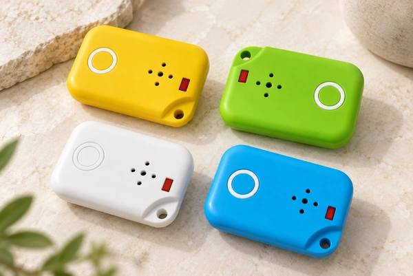
Recessed Micro USB or USB-C ports can collect dirt and need suitable sealing and support. A magnetic contact face offers a different integration option that may be easier to access for cleaning. It is not automatically superior to a properly protected USB assembly: compare the actual enclosure, exposed contacts and operating conditions.
1. Device-side Sealing Options
Rain, puddles, saliva and wet surroundings make the tracker’s water-protection design important.
A two-contact magnetic face can support a sealed device-side structure because it may allow:
An interface without a large insertion opening.
Sealing around the fixed mating contacts.
Use of appropriate silicone gaskets or overmolding.
A structure that limits relevant exposure, with corrosion resistance assessed separately.
Possible verified protection targets include the following, with the exact assembly and test conditions specified:
| Protection target | Relevant exposure to define |
|---|---|
| IP65 | A device intended for the applicable water-jet protection test; not a universal splash-only label |
| IP67 | Temporary immersion under the specified test conditions |
| IP68 | Immersion under agreed conditions more severe than IP67; not unrestricted or permanent protection in every environment |
Scroll horizontally to view every column.
These targets may be relevant to dog GPS trackers, smart collars and outdoor animal-monitoring devices. Verify the tracker and connector in the intended mated or unmated state.
GPS2. Guided Attachment for the Owner
Charging should be straightforward for the owner. A conventional insertion plug needs accurate alignment, while a suitable magnetic interface can guide the charging head toward its mating face.
Potential handling features include:
Magnetic alignment assistance.
Blind mating within the designed approach range.
Quick attachment.
Lower insertion effort.
One-handed operation where the product geometry permits it.
Bringing the correctly oriented charging head close lets the magnets guide seating. Check engagement, polarity and retention in the actual tracker.
Evaluate the handling experience with users. Convenient attachment may reduce charging difficulties, but no measured satisfaction or complaint reduction is established by this overview.
3. Controlled Cable Release
Movement around a charging cable can produce accidental pulls or entanglement. The tracker’s use instructions and charging arrangement need to account for that risk.
A magnetic connection can be designed to release at a specified pull load and direction, potentially providing:
Cable separation at the intended threshold.
Reduced pull loads on the charging-port structure.
Less force transferred to the internal PCB.
A reduction in pull-related hazards only where the complete arrangement has been assessed; it is not a guarantee of animal safety.
Application examples include:
Dog GPS trackers.
Smart pet collars.
Livestock-monitoring equipment.
Animal activity trackers.
4. Compact Wearable Integration
A collar-mounted device needs an interface compatible with its space and weight limits.
Compared with a larger candidate charging interface, a suitable two-contact design may offer:
A smaller mounting footprint.
A lower-profile structure.
Reduced connector mass.
More options for enclosure integration.
Those choices may help achieve:
Reduced PCB-space use.
A slimmer enclosure.
Appropriate wearing comfort.
The intended product appearance.
Review component weight and placement for the specific collar and animal. Lower connector mass can help the design, but comfort cannot be inferred from a weight reduction alone.
5. Mating-life Requirements
A tracker charged several times each week may accumulate many connections over a multi-year service period.
Specify and validate targets such as:
10,000–100,000 mating cycles for an appropriate design.
Contact resistance within the required limits.
The required vibration performance.
Consistent electrical behavior through the defined life test.
Face contacts avoid some insertion friction, but the spring contacts and coatings still experience movement and wear. Compare life under relevant test conditions rather than assuming that a magnetic interface is wear-free.
| Connector example | Illustrative mating-cycle range, not a universal rating |
|---|---|
| Micro USB | 5,000–10,000 in the source comparison; verify the selected assembly |
| USB Type-C | 10,000–20,000 in the source comparison; verify the selected assembly |
| Magnetic pogo interface | 10,000–100,000+ in the source comparison; verify the selected assembly |
Scroll horizontally to view every column.
A design that meets its service requirements may reduce failures and related costs. Actual warranty savings require product data and cannot be inferred directly from these illustrative cycle ranges.
6. Cleaning Outdoor Contamination
A tracker may collect contaminants such as:
Pet hair.
Dust.
Sand.
Mud.
Skin oils.
Other outdoor debris.
An accessible, flat device-side contact face may provide:
Easier inspection and cleaning.
Fewer recessed areas where debris collects.
More consistent charging when contamination is controlled.
Better maintained contact performance during service.
A flat face can be easier to wipe using an approved unpowered method. It is not free of contamination traps: spring barrels, seals and magnets may still retain particles, and attracted metal debris can obstruct or bridge contacts. Use a material-compatible cleaning routine.
7. A Charging-only Power Interface
Where the tracker needs charging at this interface rather than separate high-speed data paths, two conductive contacts may be sufficient.
A typical DC charging assignment is:
A positive supply path.
A ground or return path.
Illustrative load examples to compare with the actual device specification are:
| Device example | Illustrative charging-current requirement |
|---|---|
| Bluetooth tracker | 0.2–0.5A |
| GPS pet tracker | 0.5–1A |
| LTE pet tracker | 1–2A |
| Activity-monitoring collar | 0.3–1A |
Scroll horizontally to view every column.
The connector-selection discussion includes 1A–5A designs. Verify the specific assembly’s current rating, duty cycle and temperature rise; neither the device category nor two-contact layout establishes that capacity.
magnetic connectors8. Maintenance and Life-cycle Cost
Charging-interface faults can affect manufacturing, service and replacement costs.
A suitable design and maintenance plan may help limit:
Charging-port faults.
Mechanical-damage claims.
Corrosion-related defects.
Related customer-service work.
Returns and replacements caused by interface failures.
A simple contact arrangement may also reduce assembly complexity. Confirm manufacturing consistency and any cost benefit through the actual process and product results.
Engineering Selection Requirements
Review the following requirements when selecting a two-contact pet-tracker interface:
Electrical Requirements
Verified current capacity.
Allowed contact resistance.
Charging voltage and polarity.
Required loaded power-transfer performance.
Mechanical Requirements
Magnetic holding and release force.
Connector dimensions.
Mating-life target.
Retention and mounting strength.
Environmental Requirements
The required IP protection and test state.
Salt-spray or other relevant corrosion exposure.
Operating temperature.
Shock and vibration requirements.
Manufacturing Requirements
SMT or through-hole assembly as appropriate.
Compatibility with the intended automation.
Project-specific cost review.
A reliable supply arrangement for the selected configuration.
Conclusion
A two-contact magnetic interface can suit a charging-only pet wearable when compactness, convenient attachment and an appropriate sealing arrangement are needed. Define the tracker’s exposure, loads and mating-life target, then verify those requirements in the complete product rather than assuming that magnetic mating guarantees safety or water protection.
For engineering and procurement teams, the useful question is whether the actual connector improves fit, operation and validated reliability for the tracker. Any life-cycle savings or reduction in returns should be established from the product’s evidence. Magtor can discuss a suitable contact layout and validation plan for the stated requirements.