
Magnetic Connector Installation: Mounting and Engineering Requirements
Published on June 29, 2026
- Mounting Architecture and Installation Planning
- Why Mounting Affects Performance
- Questions to Resolve Before Assembly
- Comparing Contact Termination Methods
- Important Integration Details
Installing a magnetic interface requires a mounting plan as well as an electrical pinout. Review support, alignment tolerances, vibration, sealing and the production process together. This guide compares SMT, through-hole and wire-solder arrangements and explains how those choices affect assembly and reliability.
magnetic connectorMounting Architecture and Installation Planning
Begin with the housing geometry and the contact termination. Determine whether screw holes or other retention features are needed, and whether the contact uses SMT pads, through holes or a wire termination. Check compatibility with the device structure. Retaining the connector in a plastic housing is one common approach, but the appropriate arrangement follows the actual mechanical requirements.
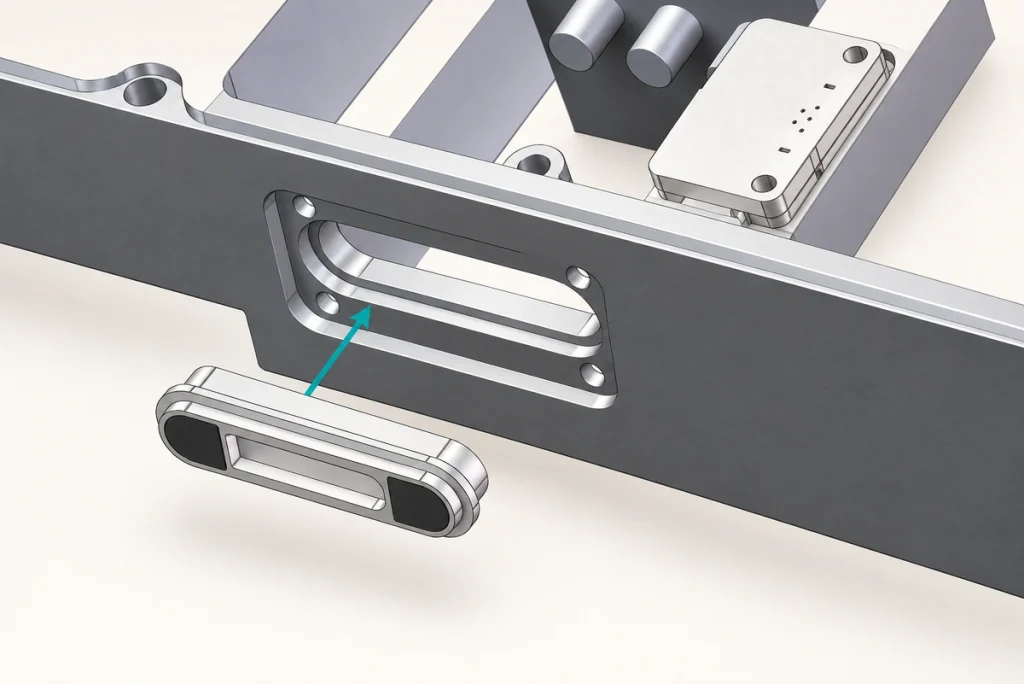
The mounting method influences more than electrical continuity. An unsuitable installation can produce unstable contact, assembly-yield problems or premature damage, with additional production cost. Engineers, product designers and buyers should evaluate that interface before choosing a connector configuration.
Why Mounting Affects Performance
Current rating, contact count and magnetic force are important, but they do not account for every field fault. Poor mounting or assembly can compromise an otherwise suitable connector, so installation needs its own review.
Possible installation-related problems include:
Solder-joint cracking under vibration.
Lifted PCB pads under excessive engagement loads.
Misalignment of the mating halves.
Loose connectors without adequate fastening.
Insufficient structural support.
Magnet or mounting damage when strong attraction loads an exposed installation.
Failure of the intended sealing arrangement.
Difficult assembly and low production yield.
Where a product targets tens of thousands of mating cycles, mounting loads and support affect contact stability, maintenance needs and user handling throughout that test life.
Questions to Resolve Before Assembly
The following engineering questions help connect installation choices to the device’s performance and purchasing requirements.
What Mechanical Loads Will Reach the Interface?
Define the following loads before choosing the mounting method:
Static loads.
Cable or user pull forces.
Lateral loads.
Vibration.
Shock and impact.
Expected user mating behavior.
Higher operating loads may require stronger support and fastening. The following qualitative examples are discussion points, not measured loads for every product in a category.
| Application example | Indicative mechanical-load category |
|---|---|
| Smartwatches | Low in the source comparison; verify actual use |
| Charging docks | Medium in the source comparison; verify actual use |
| Medical equipment | Medium to high in the source comparison; verify the specific device |
| Industrial handhelds | High in the source comparison; verify the load profile |
| Robotics | Very high in the source comparison; verify the operating loads |
Scroll horizontally to view every column.
What Mating-life Target Is Required?
Illustrative targets in this discussion include:
Consumer electronics — 10,000–30,000 cycles.
Medical equipment — 30,000+ cycles.
Industrial equipment — 30,000–100,000+ cycles.
An angled mounting can impose lateral force on the plunger and barrel during engagement. If that load falls outside the contact’s intended working conditions, it can shorten life. Check the approach direction and support geometry rather than inferring suitability from the cycle target alone.
Will the Product Encounter Vibration or Shock?
Industrial automation, drones, automotive electronics, robotics and portable medical equipment are examples where vibration or shock may affect the interface. Define the actual qualification profile for the device.
Under those conditions, inadequate PCB mounting may contribute to:
Solder fatigue.
Intermittent contact.
Increasing resistance.
Loss of connector function.
What Sealing Is Required?
For a product targeting IP65–IP68, review the following features and the exact protection state:
Connector sealing.
PCB sealing where needed.
Housing compression at the seal.
Adhesive compatibility.
Assembly tolerance stack.
A connector with a tested sealing design can still fail to protect a device when installed incorrectly. Review the connector, housing and assembly process as one protection system, with the appropriate final test.
Comparing Contact Termination Methods
The contact’s rear termination influences the assembly process, mechanical support and cost.
SMT / Surface-mount Contacts
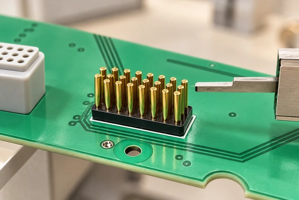
Structure
Contacts solder directly to PCB pads.
The design can fit an approved automated SMT process.
A compact footprint is possible.
The layout can suit a dense electronic assembly.
Potential Benefits
A cost-conscious volume assembly process.
Efficient assembly on a compatible line.
A useful structure for miniature products.
Support for suitable production automation.
Constraints
Pad-only retention may provide limited mechanical support.
Vibration performance depends on support and joint design.
Excessive loads can lift PCB pads.
Footprint and process control need careful definition.
Application Examples
True-wireless stereo earbuds.
Smartwatches.
Smart glasses.
Portable consumer electronics.
Through-hole / Board-insert Contacts
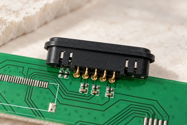
Structure
Contacts pass through PCB holes.
The joints are soldered using the specified process.
The holes and joints provide additional anchorage.
Potential Benefits
A strong anchorage option.
Support for demanding vibration requirements when qualified.
Resistance to pull-out loads through an appropriate design.
A structure that can support the required service-life target.
Constraints
The chosen assembly process may add cost.
Holes and clearances can require more PCB space.
Assembly may take longer than a comparable SMT process.
Application Examples
Industrial equipment.
Medical devices.
Charging docks.
Robotics.
Automotive electronics.
Wire-solder Contacts
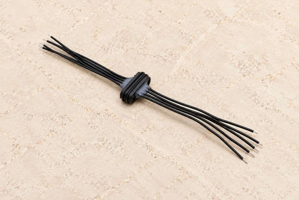
Structure
Conductors terminate directly at the connector.
Contact placement is less constrained by a local PCB footprint.
The cable supports flexible installation routes.
Potential Benefits
Flexible placement within the enclosure.
Integration into an appropriate sealing design.
Replacement and servicing where the construction permits it.
Reduced direct mechanical loading of the PCB when properly supported.
Constraints
Manual assembly can increase labor cost.
The conductors require suitable strain relief.
Cable routing and management need space and control.
Application Examples
Medical probes.
Industrial sensors.
Outdoor devices.
Wearables.
Products requiring a suitably sealed interface.
A practical starting point for comparing the options is:
Consider SMT where compactness, suitable automation and volume assembly cost are priorities.
SMTConsider through-hole anchorage where support, mating loads and vibration requirements are demanding.
Consider wire termination where placement flexibility, sealing integration or servicing needs favor a cable arrangement.
Important Integration Details
Control Mating Alignment
Magnetic guidance does not eliminate the need for a tolerance review. Excessive positioning error can cause:
Additional mating wear.
Less contact area.
Intermittent electrical engagement.
Reduced service life.
Add Appropriate Mechanical Support
For frequent mating, possible support features include:
Locating posts.
Screw fastening.
Metal brackets.
Material-compatible epoxy reinforcement where approved.
Support from the enclosure structure.
Do not ask the solder joints alone to carry loads they were not designed to withstand.
Review Magnetic Force and Exposure
Consider how installed magnets interact with nearby objects and how attraction loads their mounting. Also check temperature exposure: exceeding the selected magnet grade’s thermal limit can reduce its strength.
Illustrative holding-force ranges from the source discussion are:
| Application example | Illustrative magnetic force to validate |
|---|---|
| Wearables | 300–600 gf |
| Consumer electronics | 500–1000 gf |
| Industrial equipment | 1000–2000 gf |
| Docking systems | 1500–3000 gf |
Scroll horizontally to view every column.
Conclusion
A complete installation plan covers mounting, support, alignment, exposure and production processes alongside the electrical termination. SMT, through-hole and wire-solder arrangements each offer useful options, with different space, assembly and maintenance constraints. Define the device’s mechanical loads and mating-life target, review sealing as part of the complete enclosure, and validate the actual assembly. Early attention to these details helps reduce manufacturing risks and supports the intended connection stability without treating any mounting method as a universal guarantee.