
Magnetic Connector Reliability: What Determines Service Life?
Published on June 24, 2026
- Design Factors Behind Long-term Reliability
- Environmental Conditions to Specify
- Interpreting Service-life Examples
- Reliability Tests to Request
- Practices That Support Service Life
- Applications with Demanding Life Requirements
Repeated mating makes contact wear and long-term stability important for a magnetic interface. Reliability depends on spring-contact durability, coatings, alignment, exposure and the validation method. This guide explains what engineers and buyers should examine when selecting an assembly for an intended service life, rather than assuming that magnetic attachment alone proves reliability.
Magnetic connectorsDesign Factors Behind Long-term Reliability
The magnets are only one contributor to reliable operation. The contact system, housing and manufacturing process must work together within the specified conditions.
1. Spring-contact Durability
Where a design uses pogo contacts, their structure is central to electrical engagement.
The required contact performance includes:
Spring force within the specified range.
Suitably low contact resistance.
Fatigue performance appropriate to the life target.
Smooth compression and return after repeated use.
The example target range in this discussion is 30,000–100,000+ mating cycles for suitable spring-contact designs. Confirm the chosen model’s electrical limits, working stroke, wear criteria and test conditions before applying that range to a product.
A spring that loses restoring force can contribute to intermittent charging or communication. Investigate the actual mechanism, which may involve the spring design, working travel or operating exposure.
2. Contact-coating Quality
Engagement and release can produce friction at the mating surfaces over repeated cycles.
The coating system affects:
Contact resistance.
Resistance to mating wear.
Oxidation behavior.
Corrosion performance.
Coating features to review include:
Gold-plated mating surfaces where appropriate.
A suitable nickel underlayer.
Controlled coating thickness.
Composite coating options for the required exposure.
Gold thickness and uniformity can affect wear life and stable conduction, but increasing thickness adds cost and is not an unlimited solution. Specify the full coating stack and allowable wear for the application. A composite coating may be appropriate in particular exposure conditions after validation.
3. Mating Alignment
A magnetic arrangement can guide the approach before the contacts fully engage, with locating features controlling the final position.
The alignment design should support:
A repeatable seated position.
Limited unnecessary mechanical wear.
A manageable engagement force.
Reduced contact damage from incorrect alignment.
Good alignment limits unintended side loading on spring contacts. Repeated lateral force can damage a design intended for another mating direction; in the source example, an assembly targeting tens of thousands of cycles may fall to only a few thousand or fewer after such damage. Treat this as a failure scenario, not a universal life rating for lateral-contact interfaces.
4. Housing Materials and Support
The housing locates and supports the internal parts under the specified mechanical loads.
Material options mentioned in this overview include:
High-temperature engineering plastics.
Liquid-crystal polymer, or LCP.
Polyamide, or PA/nylon.
- PBT.
Choose the material grade for the required properties:
Dimensional stability.
Temperature resistance.
Wear behavior.
Mechanical strength.
A suitably supported housing can limit distortion and preserve alignment during service. Confirm its dimensions and material properties at the actual temperature and load conditions.
5. Magnetic-material Selection
Permanent-magnet material and exposure affect retention over the intended service period.
One material option to evaluate is:
Neodymium-iron-boron, or NdFeB.
The selected magnet should meet requirements for:
Stable holding force.
Resistance to demagnetization under the defined conditions.
Service life within its rated operating-temperature range.
A suitable neodymium magnet may retain useful performance over many years when temperature and other exposure stay within its design limits. Obtain material-grade and assembly evidence rather than assuming all magnets have the same long-term behavior.
Environmental Conditions to Specify
Premature failure can occur when actual exposure exceeds the protection provided by the connector design.
Water and Moisture
Water exposure can contribute to:
Corrosion.
Short circuits.
Higher contact resistance.
For the actual outdoor or portable application, consider whether the verified protection target should be:
IP65.
IP67.
IP68, with the specified immersion conditions.
Appropriate sealing can limit the defined exposure, but protection must be checked for the relevant parts and mated state of the assembly.
Dust and Metal Debris
The magnets can collect small ferrous particles near the contacts.
Accumulated debris can:
Prevent complete engagement.
Increase resistance.
Make charging intermittent.
A material-compatible cleaning and inspection routine helps control this buildup.
Temperature Exposure
Temperature extremes can affect:
Housing dimensions and stability.
Spring properties.
Magnetic retention.
Ask for testing over the temperature range and cycling profile required by the application. An industrial label alone does not establish that the relevant thermal validation has been performed.
Vibration and Shock
Relevant application examples include:
Industrial equipment.
Robotics.
Drones.
Automotive electronics.
These products may need vibration and shock performance beyond a simple static docking check.
Suitable retention and precise mechanical support can limit intermittent separation during movement. Verify the current-carrying contacts under the specified vibration and shock profile in the final mounting arrangement.
Interpreting Service-life Examples
Actual life depends on design and operating conditions. Use the following illustrative targets as discussion points, not general guarantees:
| Performance item | Illustrative target or evaluation condition |
|---|---|
| Mating cycles | 10,000–100,000+ for a suitable validated design |
| Contact resistance | Within the defined limits throughout the rated life test |
| Spring-force retention | Within the specified range after repeated compression |
| Magnet service period | 10+ years is an example target under defined normal-use conditions, not a universal rating |
| Gold-coating durability | Depends on the coating system, thickness and mating frequency |
Scroll horizontally to view every column.
For mission-critical equipment, review accelerated life testing alongside application-specific qualification. The test method and failure criteria must justify its relevance to the intended service conditions.
Reliability Tests to Request
Agree which reliability tests the manufacturer will perform before volume production, and request reports identifying the exact assembly and conditions.
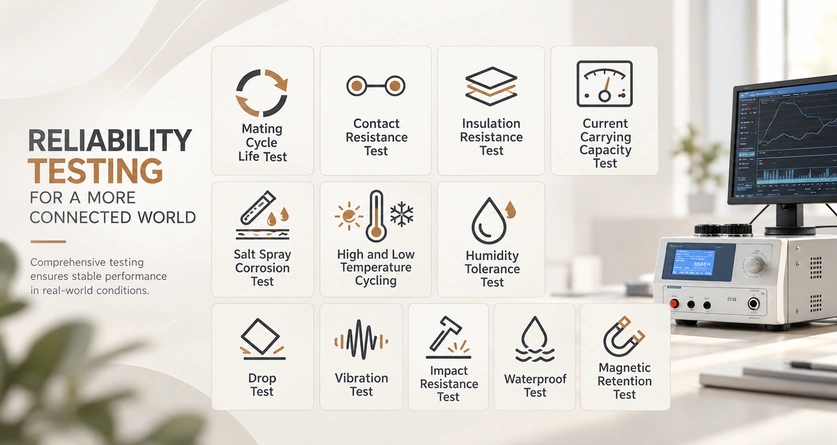
The test plan may include:
Mating-cycle life.
Contact resistance.
Insulation resistance.
Current-carrying performance.
Salt-spray corrosion exposure.
High- and low-temperature cycling.
Humidity exposure.
Drop testing.
Vibration testing.
Shock testing.
Water-protection testing.
Magnetic-force retention.
These checks are useful when their loads, exposures and acceptance limits represent the intended application. Passing unrelated tests does not establish performance in every environment.
Practices That Support Service Life
Operating and maintenance practices should match the selected connector’s instructions and exposure conditions.
Keep the Mating Faces Clean
Remove dust, attracted particles and moisture using the approved unpowered cleaning method and material-compatible tools.
Limit Unintended Side Loads
Follow the intended mating and release directions. Excessive angled pulling or sideways engagement can increase wear or damage spring contacts despite magnetic guidance.
Stay Within the Verified Limits
Do not exceed the assembly’s specified:
Current and duty-cycle limits.
Operating voltage.
Temperature range.
Mechanical load limits.
Respecting these limits helps control overheating and wear, while the complete product still needs the required protection and qualification.
Specify Suitable Protection
For outdoor, industrial or medical use, select sealing and corrosion protection appropriate to the actual exposure and cleaning process.
Review Manufacturing Capability
Manufacturing consistency depends on controls such as:
Precision machining.
Controlled dimensional tolerances.
Specified material grades.
Consistent coating processes.
Quality checks appropriate to the assembly.
Evaluate the manufacturer’s relevant capability, traceability and test evidence. Experience can help the review but does not replace verification of the ordered configuration.
Applications with Demanding Life Requirements
Long-term contact stability can be important in products such as:
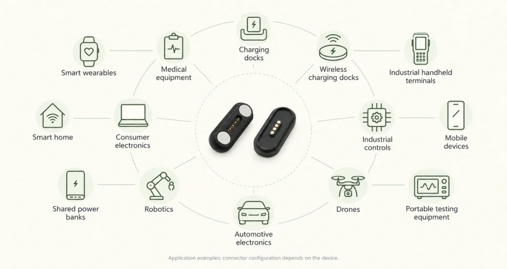
Smart wearables.
Medical equipment.
Charging docks.
Industrial handheld terminals.
Smart-home products.
Consumer electronics.
Shared power banks.
Robotics.
Automotive electronics.
Drones.
Portable test equipment.
Some of these products need thousands of reliable connections over their service period. Define the actual number and operating conditions for the particular device.
Conclusion
A magnetic interface can meet a demanding service-life target when its spring contacts, coatings, alignment and housing are suited to the application. The illustrative 10,000–100,000+ cycle range depends on the exact design, exposure and validation criteria. Review resistance and mechanical behavior through the rated life test rather than relying on a premium label.
For a long-life project, combine contact and coating review with sealing requirements and manufacturer test evidence. A well-matched assembly can reduce faults and maintenance needs, but the conclusion must follow the specific product’s qualification rather than a general claim about all magnetic connectors.