
Inside a Magnetic Connector: Structure and Operation
Published on June 10, 2026
- The Magnetic Interface and Its Functions
- Components Inside the Assembly
- The Mating Sequence
- The Role of Gold Plating
- Features to Review for Reliability
- Failure Modes to Investigate
- Application Examples
A magnetic interface combines magnetic guidance with a conductive contact system. Its magnets, contacts, springs, housing and coatings each affect how it performs. This structure overview explains the parts and operating sequence, then identifies reliability features and failure modes to consider when selecting or examining an assembly.
magnetic connectorThe Magnetic Interface and Its Functions
A magnetic connector uses magnetic attraction to guide two mating assemblies into electrical contact. Its implemented functions depend on the contact assignment and system design, and may include:
A power-only interface.
A data-only interface.
Power and supported data together.
High-current power transfer with any required charging-control signals.
Supported USB, UART, I²C or custom communication paths, when designed and validated for them.
Magnetic face-contact mating can simplify attachment and avoid some of the insertion friction of conventional ports. The contacts still require an appropriate wear and life-cycle design.
Components Inside the Assembly
Several precision parts work together to establish the electrical paths and mating position. A two-contact interface provides a simple example of that cooperation, although larger arrays may add different contact and alignment arrangements.
two-contact magnetic connector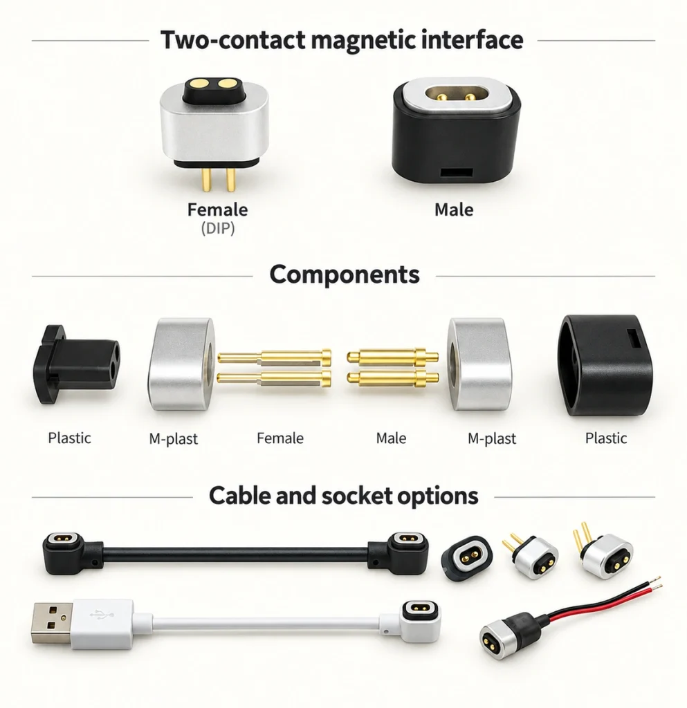
1. Magnets and Retention
The magnets provide the recognizable guiding and holding action of the interface.
Their intended functions may include:
Guiding the halves during engagement.
Holding the seated structure so the spring contacts remain compressed.
Resisting unintended separation within the design’s load limits.
Making attachment easier for the user.
Magnetic-material options to evaluate include:
Neodymium-iron-boron, or NdFeB.
NdFeBFerrite.
Other rare-earth magnetic alloys.
NdFeB can provide substantial magnetic force in a compact volume, which makes it useful in small interfaces. Its permitted temperature depends on the material grade and assembly; exceeding that limit can reduce magnetic strength. Confirm both the manufacturing and operating thermal conditions.
2. Conductive Contacts
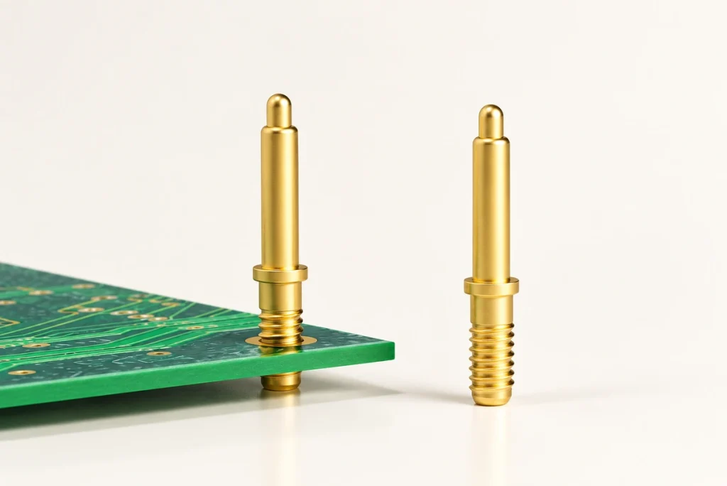
The pogo contacts carry electrical current and the signals assigned to their paths.
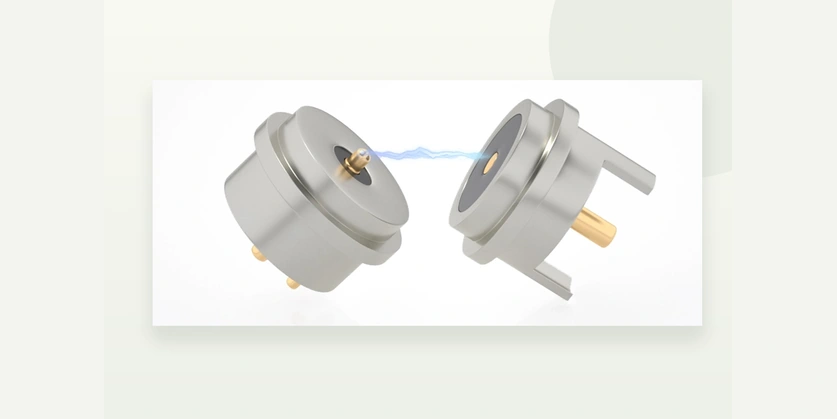
The mating arrangement may use:
Spring-loaded pogo contacts.
Fixed copper contacts or pillars.
Possible contact-body materials include:
Brass.
Beryllium copper.
Phosphor bronze.
The coating system is selected for electrical contact and environmental performance. Materials mentioned in this design discussion include:
Gold.
Nickel.
Palladium alloys.
Rhodium-ruthenium coatings.
Platinum.
For severe corrosion exposure, a composite coating system may be considered instead of simply increasing one layer’s thickness. The appropriate stack and thickness still need to be specified and validated for the contacts and environment.
3. Spring Mechanism
Inside a pogo contact, the spring establishes force as the plunger compresses through its working travel.
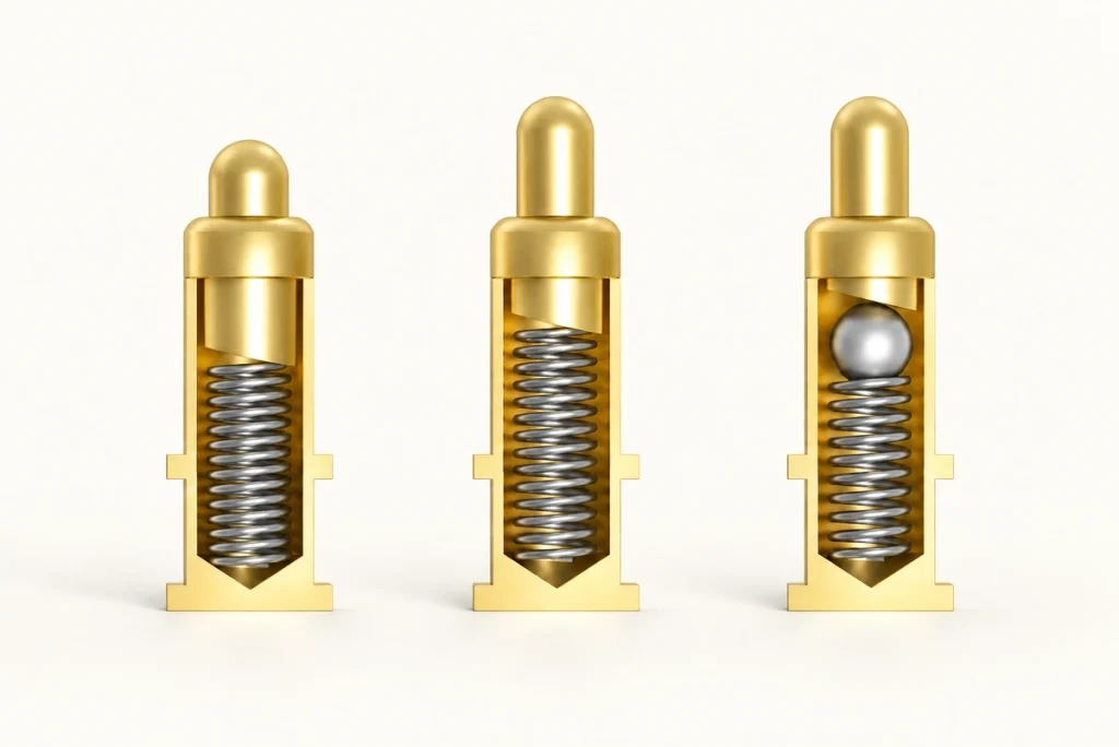
Within the specified operating range, spring compliance can:
Accommodate the manufacturing tolerance stack.
Maintain pressure at the electrical interface.
Accommodate the permitted movement from vibration or shock.
Limit contact-resistance changes caused by loss of pressure.
Spring design, materials and working stroke are important to repeated-mating life. Evaluate them together with the complete contact rather than assuming that spring loading guarantees reliability.
4. Mechanical Alignment Features
Magnets may guide the approach while mechanical features locate the seated position. The combination should align contacts throughout the specified tolerance range.
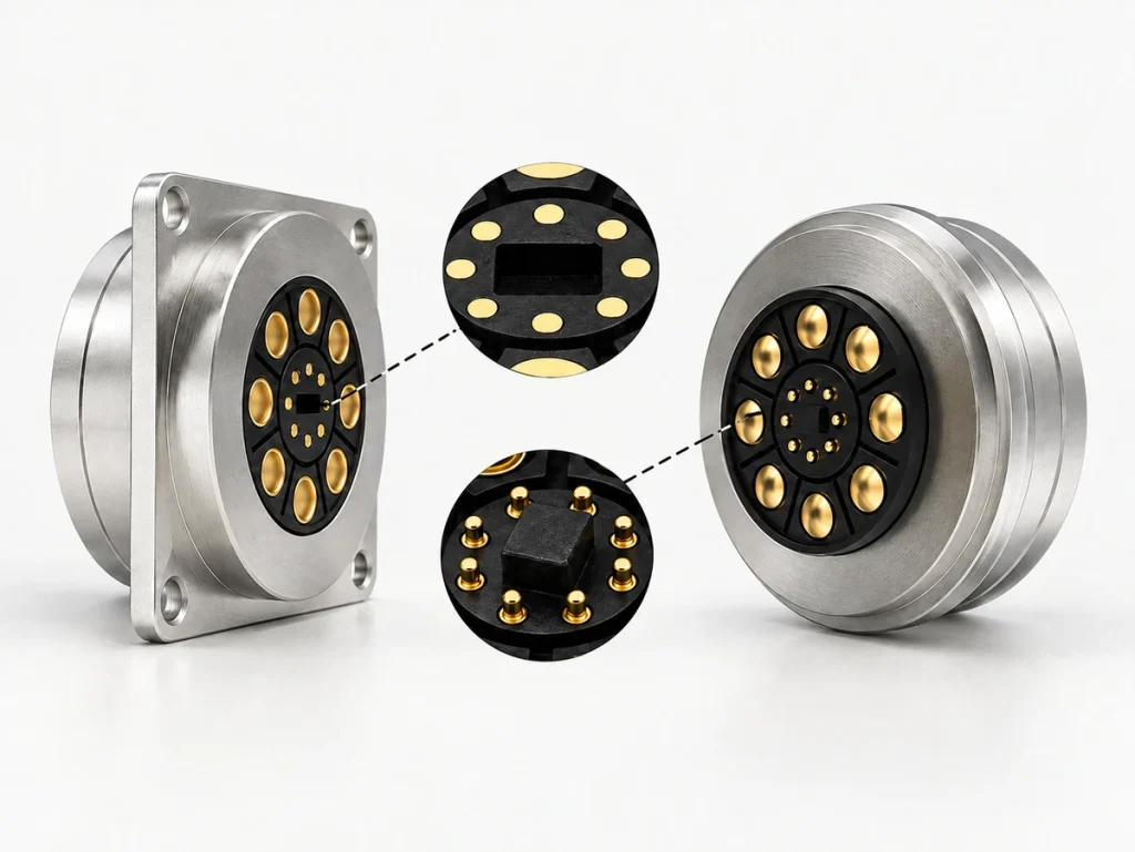
Possible locating features include:
Guide grooves.
Positioning slots.
Raised locating ribs.
Keyed geometry.
These features can improve mating accuracy and reduce contact misalignment when their geometry and tolerances are correctly defined.
5. Cable and PCB Termination
The rear electrical connection may use:
Soldered wire terminations.
PCB surface-mount terminals.
Through-hole solder joints.
Flexible-circuit connections.
Review this termination area for both electrical continuity and mechanical loading. Appropriate support and strain relief help prevent use forces from damaging the joints.
The Mating Sequence
When correctly oriented mating halves approach, the magnetic arrangement begins to draw them toward engagement.
A typical sequence has five stages:
Stage 1: Attraction
The attractive force draws the intended mating faces toward one another.
Stage 2: Alignment
The magnetic arrangement and mechanical guides position the corresponding contacts.
Stage 3: Engagement
The conductive surfaces meet, and spring-loaded contacts compress to establish the assigned paths.
Stage 4: Retention
The magnets retain the seated assembly while the springs supply contact force. Stable power or signals depend on that engagement and the validated electrical design.
Stage 5: Release
A sufficient force in the intended release direction separates the magnetic interface. Whether this avoids damage depends on the release threshold, load direction and surrounding structure, so verify the breakaway behavior in the product.
The Role of Gold Plating
Gold-plated mating surfaces are one contact-system option worth examining in a connector’s construction.
A suitable gold-plating system may support:
Low contact resistance.
Stable conduction at the mating surface.
Resistance to the specified corrosion exposure.
Wear performance suited to the mating-life target.
Consistent signal contact when the whole interface meets its requirements.
Coating selection is especially important where humidity, sweat or chemicals affect the contacts. Validate the complete plating stack and its wear behavior for the expected exposure.
Features to Review for Reliability
When examining a connector for a demanding application, assess the following features rather than relying on an industrial-grade label:
Corrosion Protection
Suitable protective coatings can limit oxidation and corrosion under the defined exposure and service conditions.
Repeated-mating Durability
Possible design targets include:
10,000 cycles.
20,000 cycles.
50,000 or more mating cycles where supported by the assembly’s test evidence.
Sealing Features
Depending on the interface, sealing provisions may include:
Silicone gaskets.
O-rings.
Overmolded sealing structures.
Such features can form part of a design targeting IP65 or IP67. The final rating requires the appropriate test of the specified assembly and protection state; the presence of a gasket is not enough to prove it.
Vibration Performance
Spring compliance and suitable magnetic retention can support mobile or industrial use within defined limits. Test the assembly against the required vibration profile and mounting arrangement.
Failure Modes to Investigate
Inspection of a failed assembly should consider the following possible mechanisms:
Contact Wear
Repeated engagement can progressively remove the coating from the mating surface.
Contamination
Dust, oil and other debris may accumulate on the contact faces and interrupt conduction.
Loss of Magnetic Strength
Exposure beyond the magnet’s temperature limit can reduce retention performance.
Spring Degradation
An unsuitable spring, excessive working travel or extended cycling can reduce the contact’s restoring force.
Faulty Solder Termination
Defective assembly or unsupported joints can cause unstable electrical paths.
Identifying the actual failure mechanism helps guide a design or process correction; a damaged contact alone does not establish which mechanism caused it.
Application Examples
Magnetic interfaces can be evaluated for products such as:
Smartwatches.
Bluetooth earphones.
AR/VR devices.
Medical equipment.
Industrial sensors.
Robotics.
Smart-home products.
Portable charging equipment.
Shared power banks.
Automotive electronics.
Across these categories, convenient mating is useful only when the interface also satisfies the application’s electrical, mechanical and environmental requirements.
Conclusion
The outer magnetic connection depends on a coordinated set of magnets, conductive contacts, springs, insulation and locating features. Their dimensions, materials and assembly processes determine contact stability, mechanical behavior and handling. Review the complete structure against the product’s requirements rather than judging reliability by a single component.
Understanding this construction helps engineers and buyers ask more useful questions when selecting or customizing an interface. An actual teardown can support that review, but measurements and application-specific testing are still needed to substantiate performance.