
Installing a Magnetic Connector: A Step-by-step Guide
Published on June 8, 2026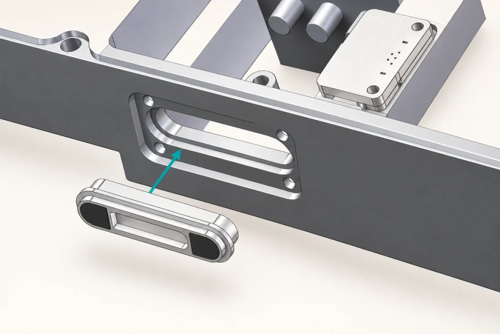
- Identify the Connector Components
- Prepare the Required Tools
- 1. Confirm the Mounting Orientation
- 2. Secure the Connector in the Enclosure
- 3. Terminate the PCB or Cable Connection
- 4. Inspect Magnetic Engagement
- 5. Test the Electrical Functions
- 6. Inspect Reliability-related Features
- Installation Errors to Avoid
- Practices for Continued Service
- Installation Questions
Magnetic interfaces can make charging and supported data connections convenient, but installation affects alignment, contact resistance and service life. This guide covers the mounting, termination and inspection steps needed to integrate an appropriate connector. Follow the selected assembly’s drawings and process limits throughout.
Magnetic connectorsIdentify the Connector Components
Before assembly, identify the parts and the function of each component:
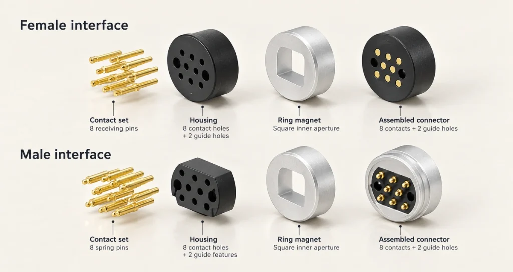
Electrical contacts, such as pogo pins or fixed copper contacts.
Magnets used for positioning and retention.
A plastic or metal housing.
The cable termination or PCB interface.
The mounting features that locate the connector in the device enclosure.
Depending on its structure, the interface may mount on a PCB, sit within the enclosure or terminate a cable assembly. Use the installation method intended for that design.
PCBPrepare the Required Tools
The mounting method determines the exact tools. Typical items to prepare include:
The specified magnetic connector assembly.
Suitable soldering equipment where PCB termination is required.
A screwdriver or the relevant assembly fixture.
A multimeter.
A clean cloth or material-compatible alcohol wipes.
Protective gloves if the assembly process calls for them.
Confirm that voltage, current rating and contact assignment match the device before starting. Then choose tools and materials suited to the actual housing and electrical termination process, rather than assuming every magnetic connector installs in the same way.
1. Confirm the Mounting Orientation
Magnetic guidance during use does not replace an orientation check during assembly.

Verify each of the following:
The contact layout matches the mating half.
Positive and negative power paths are assigned correctly.
Data contacts meet their corresponding paths.
The magnet polarities match the intended orientation.
An incorrect orientation can prevent charging, disrupt communication or damage connected electronics. Some magnetic arrangements repel an incorrectly oriented half and help avoid reverse mating, but this protection must be verified for the actual design; it is not an automatic property of every magnetic interface.
2. Secure the Connector in the Enclosure
Place the connector in the mounting feature specified by the housing drawing. Depending on the design, retention may use a snap fit, screw holes or another defined assembly method.
For an enclosure-mounted interface:
Locate the connector in its designated slot.
Keep the required mating face accessible.
Check the specified flushness and position relative to the enclosure.
Secure it using the approved screws, clips, adhesive or overmolding process, as applicable.
One integration approach used in customer projects places the connector behind an outer device casing, exposing only the mating face. Magtor can discuss that arrangement where it suits the housing; secure retention and contact stability still need to be checked in the completed assembly.
Magtor3. Terminate the PCB or Cable Connection
Choose the termination process specified for the connector. Cable layouts may use a 90° or 180° exit, and that direction should be checked against the available space and strain-relief arrangement.
PCB Termination
Align the solder pads with the specified footprint.
Follow the manufacturer’s approved soldering-temperature profile.
Avoid exceeding the permitted heat exposure.
Inspect joints for bridging and cold-joint defects.
Cable Termination
Connect each conductor according to the verified pinout.
Check power polarity before energizing the assembly.
Secure strain relief so operating loads do not pull on the electrical termination.
Correct termination is part of the low-resistance current path and helps avoid intermittent operation.
4. Inspect Magnetic Engagement
Mate the installed connector with its intended counterpart and inspect:
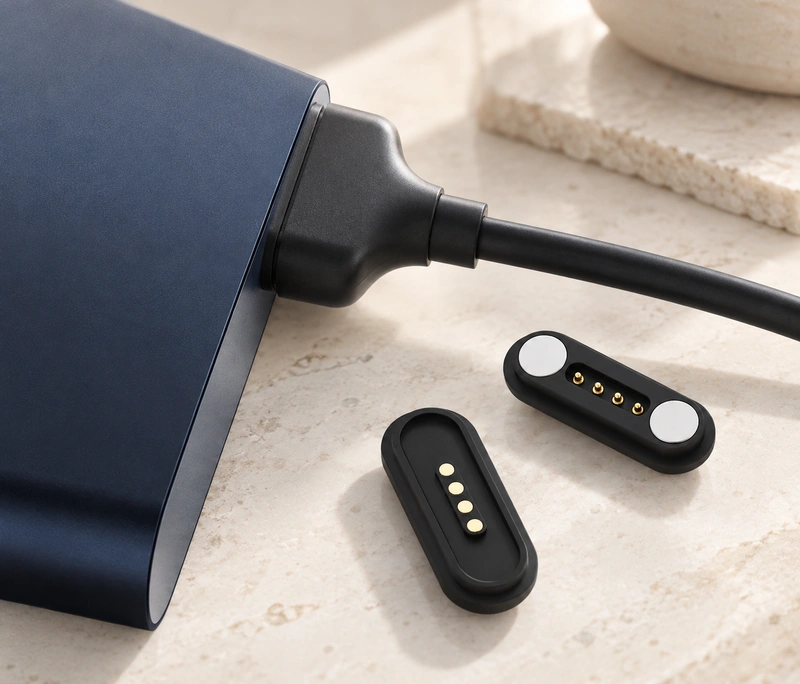
Alignment accuracy at engagement.
The specified magnetic holding force.
Consistent engagement of all contacts.
Smooth attachment and release.
The halves should settle into their intended position without excessive manual correction. Where magnetic self-alignment is part of the design, verify it at the approach positions and tolerances expected in use.
5. Test the Electrical Functions
Perform the required functional checks before releasing the assembled product for use.
The test plan may include:
Continuity
Verify that every assigned contact has the intended electrical path.
Contact Resistance
Measure resistance against the specification for the complete connection.
Loaded Power Transfer
Check voltage stability and current-carrying performance under the defined load.
Data Communication
For a data-capable assembly, test the implemented communication function and signal performance in the system.
6. Inspect Reliability-related Features
Products that connect frequently need particular attention to the features that support their mating-life target.
Inspect the following:
Consistent magnetic retention.
Contact pressure within the design requirements.
Correct sealing where water protection is specified.
No unintended looseness or connector wobble.
Smooth engagement through repeated mating checks.
Suitable designs may target tens of thousands of mating cycles, and specialized assemblies may target hundreds of thousands. Those examples require an appropriate pogo-contact structure, plating and associated features, followed by validation of the exact assembly and conditions; they are not installation guarantees.
Installation Errors to Avoid
Wrong Contact Assignment
Reverse supply polarity can damage electronics. Verify the number of contacts and the function of every path before finalizing the design. A mixed-pitch arrangement may help meet the electrical and cost requirements, but it must still provide correct routing, spacing and mating geometry.
Excessive Assembly Heat
Too much heat can damage the spring mechanism, coating or magnet performance. A magnet may lose strength if its material-specific temperature limit is exceeded. Confirm both the assembly-process profile and the later operating temperature before selecting the magnetic arrangement.
Inadequate Mechanical Support
Loose or unsuitable mounting can contribute to vibration-related failures. Particularly demanding or safety-critical vehicle functions, such as braking or central-control systems, need an application-specific qualification review; a pogo-contact arrangement may be unsuitable if it cannot meet the required vibration and reliability criteria.
Contaminated Mating Surfaces
Dust, grease and other debris can increase contact resistance. Material that blocks the contact face entirely can prevent conduction, so inspect and clean using the method approved for the assembly materials.
Unspecified Environmental Exposure
Outdoor, medical and industrial use may add sealing, corrosion-resistance or high-current requirements. Corrosion can cause both unstable electrical contact and physical pin damage, so the environmental specification needs to be addressed during design and installation.
Practices for Continued Service
To support the intended service life:
Keep the mating surfaces clean.
Avoid excessive side loading during engagement.
Operate within the manufacturer’s verified current limits.
Inspect periodically where conditions are harsh.
Use a connector designed and validated for the application.
Correct installation and an appropriate connector design are both necessary; careful assembly cannot make an unsuitable part meet the application requirements.
Installation Questions
Which Tools Are Needed for Installation?
Many designs use standard assembly or soldering equipment, but the required tools depend on the mounting and termination method. Check the part’s drawing and approved assembly process.
Can the Connector Mount Directly on a PCB?
PCB-mounted variants may use SMT or through-hole termination. Confirm the footprint, orientation and soldering limits of the specific connector.
How Can Electrical Polarity Be Checked?
Use the manufacturer’s verified pinout and check the unpowered assembly with a multimeter before applying power. Magnetic attraction alone does not prove correct electrical polarity.
Can a Magnetic Interface Be Used in a Sealed Device?
IP65 and IP67 designs are examples available for suitable outdoor or wearable applications. Confirm which parts and assembly states are protected, and validate the required exposure rather than treating every magnetic interface as sealed.
When Should the Interface Be Inspected?
For frequent mating or harsh use, periodically inspect contacts, magnets and engagement behavior according to the assembly’s maintenance instructions.
Conclusion
Reliable integration requires a verified orientation, secure mounting, correct termination and electrical testing. Check the magnetic and contact engagement in the final enclosure, then follow the approved operating and maintenance limits. These steps help the assembly meet its intended performance without replacing product-level qualification.
Wearables, charging docks, medical equipment, smart-home products and industrial systems can all use a suitably installed magnetic interface. Its actual service period and maintenance needs depend on the selected design, validated life and operating environment; installation alone cannot guarantee years of operation.