
What Is a Magnetic Connector? Design, Use and Purchasing
Published on June 2, 2026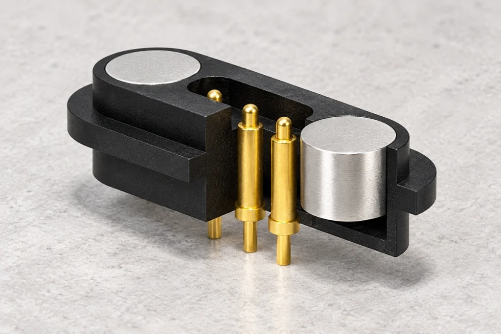
- How Magnetic Mating Makes an Electrical Connection
- Practical Benefits of Magnetic Interfaces
- Industry Applications and Design Advantages
- Maintaining Contacts and Magnetic Mating Surfaces
- Wholesale Pricing and Minimum Order Quantities
- Compliance Documentation and Production Lead Times
Magnets in a magnetic connector bring its contacts into alignment and join the mating halves for quick power or data transfer. This approach is useful for frequent docking, connections made without precise visual alignment, and quick release. Examples include charging docks, portable devices, medical equipment and industrial sensors.
How Magnetic Mating Makes an Electrical Connection
The interface combines magnetic retention with an electrical path formed by pins and pads. As the male and female halves approach one another, magnets pull them into the intended orientation, often with features that prevent incorrect mating. Spring-loaded pins or flat contacts then complete the circuit. Depending on the design, shielding, seals or a floating mount can help accommodate alignment errors and vibration.
Magnetic connectors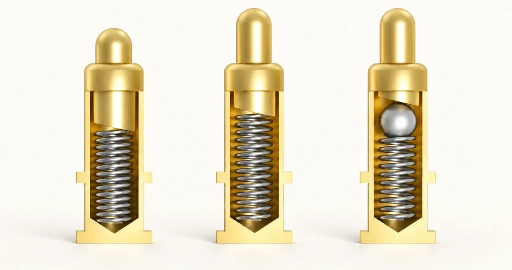
Key design details to review
Contact arrangement: pogo pins, flat pads or a hybrid interface for power and signals.
Retention: the magnetic pull force and resistance to lateral loads.
Electrical requirements: rated current, contact resistance, pin count and data capability.
contact resistanceEnvironmental protection: sealing for the target IP rating, corrosion resistance and tolerance of debris.
IPRelease safety: a specified breakaway force to help reduce damage to the cable or device.
The Mating and Release Sequence
Approach: bring the device or plug close to its mating half.
Magnetic capture: the magnets engage and center the halves in their keyed orientation.
Electrical engagement: pogo pins compress, or pads touch, to establish the circuit.
Retention: housing features resist twisting and shear, while the magnets provide normal holding force.
Release: the joint separates when a pull or lateral load exceeds the designed breakaway threshold.
| Parameter | Why it matters | Typical options |
|---|---|---|
| Alignment method | Determines blind-mate success | Magnet polarity + Structural Control |
| Contact type | Impacts wear and stability | Pogo pin / pad / mixed |
| Current & voltage | Prevents overheating/arc risk | Low-power to high-current power pins |
| Data support | Ensures signal integrity | USB, UART, I²C, LVDS (design-dependent) |
| Durability | Defines lifecycle cost | Cycle life based on plating + spring design |
| Environment | Reliability in field use | IP-rated sealing, anti-corrosion plating |
Scroll horizontally to view every column.
Design note: contact plating and a pull-force setting that does not match the actual lateral load can both contribute to connector faults. Simulate the intended mating and loading conditions before the design is finalized. The source attributes this observation to laboratory testing; no new-subject report is supplied.
Practical Benefits of Magnetic Interfaces
A magnetic interface can make connection more intuitive, reduce wear from forced insertion and provide a release mechanism that helps protect the device. Consumer products commonly use 4-pin or 2-pin magnetic arrangements to fit compact housings and support repeated blind mating. When the complete interface is designed correctly, it can also support a small form factor and a sealing strategy that is better suited to the application than an open port.
magnetic 4pin connector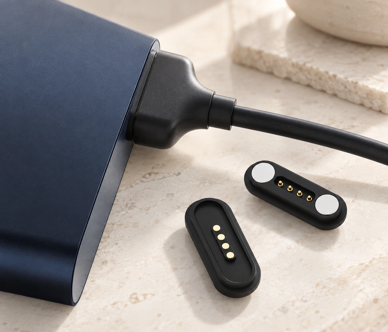
Comparing Magnetic Interfaces with Conventional Plugs
| Benefit | Magnetic connector | Traditional plug |
|---|---|---|
| Ease of use | Self-aligning, quick attach | Requires orientation + insertion force |
| Safety | Breakaway reduces damage | Can yank device/port |
| Wear | Lower mechanical insertion wear | Port wear from repeated insertion |
| Docking | Excellent for blind-mate | Often needs guides/tight tolerances |
| Sealing strategy | Can keep device side flatter/closed | Open port can be ingress point |
Scroll horizontally to view every column.
Application note: magnetic guidance is particularly useful when gloves, low light or movement make manual alignment difficult. In such situations it can reduce the risk of bent pins and damaged receptacles compared with a conventional connection, provided the mating geometry is appropriate.
Industry Applications and Design Advantages

Consumer Electronics
Examples include smartphones, tablets, smartwatches, wireless earbuds, portable speakers and charging docks.
The interface simplifies charging and helps limit port damage from repeated plugging and unplugging.
Wearable Devices
Fitness trackers, smart rings, AI smart glasses and health-monitoring devices are common examples.
A small, lightweight connection saves space and makes charging more convenient.
Medical Equipment
Potential uses include portable diagnostic devices, patient monitors, rehabilitation equipment and wearable medical electronics.
Design goals include a stable connection, straightforward cleaning and convenient maintenance.
Industrial Equipment
Examples include industrial sensors, handheld terminals, automation equipment, inspection instruments, portable test equipment and data-collection devices.
A suitable design allows quick connection in demanding environments, addresses vibration and shock, and reduces maintenance-related downtime.
Automotive Electronics
EV accessories, diagnostic equipment, cockpit systems and vehicle electronics are example applications.
These applications can benefit from easier servicing, vibration resistance and stable power delivery when the interface is specified for the load.
Smart Home Devices
Smart locks, cameras, lights, robots and other IoT devices can use magnetic connections.
The design can improve ease of use and appearance, support water protection and reduce mechanical wear.
Robotics and Automation
Examples are automated guided vehicles, robots, docking stations and modular systems.
Automatic alignment and repeatable engagement can make docking and module changes more efficient.
Application note: fast engagement, frequent mating, compact dimensions and reliable electrical performance are common reasons to select a magnetic interface. Self-alignment improves handling and can reduce the mechanical wear associated with a traditional plug.
Maintaining Contacts and Magnetic Mating Surfaces
Keep contact surfaces clean, remove accumulated ferrous particles, and look for coating wear or pitting. Clean without abrasive materials, and keep the mating faces dry and free from oil. More frequent inspection may be needed around metalworking operations, outdoors or in vibration-prone environments, where contamination and small repeated movements are common. Follow the specified maintenance method for the particular assembly.
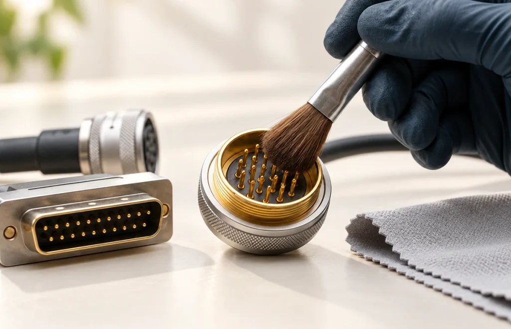
A Five-Step Maintenance Check
Inspect visually for debris, corrosion and contact discoloration.
Remove loose debris with compressed air or a soft swab that does not shed lint, as permitted by the assembly’s maintenance instructions.
For contacts compatible with this method, use a light application of IPA (isopropyl alcohol); avoid abrasive cleaning.
isopropyl alcoholRemove ferrous particles from the magnet face so they cannot keep the mating halves apart.
Check that charging or data transfer remains stable, and watch for unusual heating or interruptions.
Maintenance note: fine metal particles on the magnet face, damaged plating and incorrect alignment can all cause faults. The actual operating environment therefore needs to inform the connector design and its maintenance plan.
Wholesale Pricing and Minimum Order Quantities
Pricing and MOQ depend on the pin count, current rating, coating, cable-assembly requirements, molding and relevant certification needs. Magtor prepares a quotation from the BOM and target specification, then confirms the MOQ for a standard or custom design. Drawings, specifications and expected annual volume are needed to prepare meaningful quantity-based pricing.
MagtorInputs Needed for a Quotation
| Input | Why it affects price/MOQ |
|---|---|
| Pin count & pitch | Drives tooling complexity and yield |
| Current + temperature rise limits | Changes contact design and materials |
| Plating spec (e.g., Au thickness) | Major cost driver for durability |
| Cable length/overmold/strain relief | Impacts assembly labor and tooling |
| IP/sealing requirements | Adds gasket/structure validation |
| Custom tooling vs. standard | Determines MOQ and NRE |
Scroll horizontally to view every column.
Quotation note: a rated current alone is not enough to select the contact. Ambient temperature and corrosion requirements also affect the required contact size. Supplying those conditions helps avoid a design that is either insufficient or unnecessarily costly, with consequences for both price and MOQ.
Compliance Documentation and Production Lead Times
Materials can be specified for the applicable RoHS and ISO-related requirements, with documentation matched to the finalized BOM. The relevant ISO standard and scope must be identified; this wording does not establish a product certificate. Timing depends on a standard or custom design, tooling, validation tests and available production capacity. The schedule is confirmed after DFM review and sampling.
RoHSThe Lead-Time Planning Sequence
Specification and DFM: agree the interface, ratings, plating and operating-environment targets.
Sampling and EVT: build prototypes and check electrical and mechanical performance.
DVT and PVT, where needed: assess reliability, fit and finish, and validate the process.
Volume production: schedule the build around material availability and the agreed quality plan.
Configuration note: changes to the BOM, especially coatings or polymers, can introduce errors. Once the required documentation and reliability checks are accepted, controlling the approved drawings helps prevent those changes from entering production unintentionally.
A magnetic connector can provide a quick, self-aligning connection with a planned release behavior when its electrical, mechanical and environmental requirements are specified and validated together.