
How Magnetic Connectors Are Produced and Checked
Published on June 3, 2026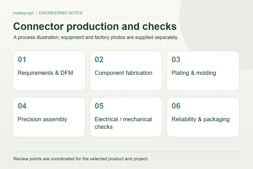
- The Complete Magnetic Connector Production Flow
- Manufacturing Controls That Affect Connector Performance
- Why Consistent Production Control Matters
- Quality Gates and Checks at Each Production Stage
Producing a magnetic connector involves a sequence of controlled operations: DFM review, fabrication of components, contact plating, molding, accurate assembly, testing, reliability validation and packaging. Checks throughout that sequence are used to control mating force, contact resistance and repeatable performance.
The Complete Magnetic Connector Production Flow
A magnetic connector is an electromechanical assembly whose magnetic circuit, contacts, housing and seals, and cable or PCB termination must work together. The production flow therefore controls four key results: accurate alignment, the required magnetic retention, low contact resistance and protection against corrosion.
magnetic connectorA typical production sequence and its quality checkpoints
| Stage | What happens | Key quality checkpoints (examples) |
|---|---|---|
| 1) Requirement intake & DFM | Define current, voltage, pin count, pitch, IP rating, cycle life, plating spec | DFM approval, tolerance stack-up, risk review (FMEA) |
| 2) Tooling & samples | Build stamping/mold tools; pilot samples | First Article Inspection (FAI), CPK plan, gauge R&R |
| 3) Metal parts fabrication | Stamp/machine contacts, shells, shields | Dimensional inspection, burr control, hardness check |
| 4) Magnet procurement & incoming | Select grade/coating (NdFeB/SmCo/ferrite), orientation needs | Incoming IQC: grade verification, coating integrity, magnetic flux sampling |
| 5) Plating | Ni/Au (or Sn) plating for contacts; anti-corrosion layers | Plating thickness (XRF), adhesion, porosity, salt-spray sampling |
| 6) Housing molding / overmolding | LCP/PA/PBT molding; cable overmold; sealing features | Warp/flash inspection, CTQ dimensions, IP feature checks |
| 7) Assembly & magnetization | Insert contacts, springs/pogo, magnets; magnetize if required; adhesive cure | Polarity/orientation verification, positional accuracy, pull/retention checks |
| 8) Electrical testing | Continuity, contact resistance, insulation, Hi-Pot | 100% continuity; CR sampling/100% per spec; Hi-Pot per rating |
| 9) Mechanical & reliability | Mating cycles, vibration, thermal shock, corrosion, ESD (as applicable) | Cycle-life report, vibration/fatigue results, environmental pass/fail |
| 10) Final QC & packaging | Visual, labeling, traceability, packing | AQL inspection, lot traceability, packaging drop test (if required) |
Scroll horizontally to view every column.
Production note: damage to pins during assembly can be a major source of lost yield. In-line polarity fixtures and pass/fail alignment gauges help control reverse magnetic leakage and keep mating force and contact resistance more consistent between batches. The source presents this as laboratory experience; no new-subject test report is supplied.
Manufacturing Controls That Affect Connector Performance
The mating halves self-align only when materials and dimensional tolerances are controlled together. Their plated electrical contacts, often pogo pins or leaf contacts, must then make a reliable connection. Metal forming, precision plating, molding or overmolding and aligned assembly are followed by electrical and mechanical checks to assess resistance, magnetic hold and durability.
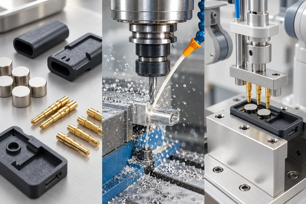
Linking the Operating Principle to Production Controls
Magnetic alignment depends on the magnet grade, polarity and placement tolerance, which together determine how the halves center themselves.
Contact geometry, spring pressure and coating thickness affect the electrical path, including contact resistance and wear.
Housing resin, seals or overmolding, and the coating’s corrosion resistance influence environmental protection, IP performance and useful life.
| Functional requirement | Manufacturing lever | Typical verification |
|---|---|---|
| Stable attraction/holding force | Magnet grade, air-gap control, placement tolerance | Pull-force test, polarity check |
| Low contact resistance | Contact force, plating (Au thickness), flatness | Contact resistance test (mΩ) |
| Long cycle life | Wear pair selection, plating hardness, spring design | Mating cycle test |
| Corrosion resistance | Gold plating + composite coating | Salt spray / Resistant to sweat electrolysis |
Scroll horizontally to view every column.
Plating note: a coating that is too thin on a high-current contact can contribute to intermittent faults. For demanding environments, the coating design needs to be assessed against the operating conditions.
Why Consistent Production Control Matters
A controlled process makes magnetic mating more predictable, reduces damage from incorrect engagement and supports consistent contact resistance as volumes grow. For brands and system integrators, better production repeatability can improve yield and reduce returns. Traceable quality records and reliability reports also give a clearer basis for documenting applicable compliance requirements.

Connecting Production Capability with Practical Benefits
| Benefit | What enables it in production | Why it matters |
|---|---|---|
| Fast, intuitive mating | Tight magnet placement + polarity control | Better UX, fewer user errors |
| Reduced port wear | Spring contacts + robust plating | Longer product life |
| Consistent performance at scale | CTQ gauges + 100% electrical tests | Lower field failure rate |
| Better corrosion tolerance | Correct Ni/Au stack + sealing/overmold | Fewer oxidation-related issues |
| Easier supplier management | Lot traceability + defined checkpoints | Faster root-cause & corrective action |
Scroll horizontally to view every column.
Process note: clear steps and careful control of the details at every stage help reduce defects caused by differences in how operators carry out the work.
Quality Gates and Checks at Each Production Stage
The reference magnetic-connector flow uses measurable gates: DFM and FAI; incoming checks for magnets, metals and resins; stamping and molding; plating control; assembly with polarity and alignment fixtures; 100% electrical testing; reliability sampling; and final AQL inspection with traceable packaging. Each gate is intended to catch faults before further work is added, helping protect both the schedule and production cost.
Magtor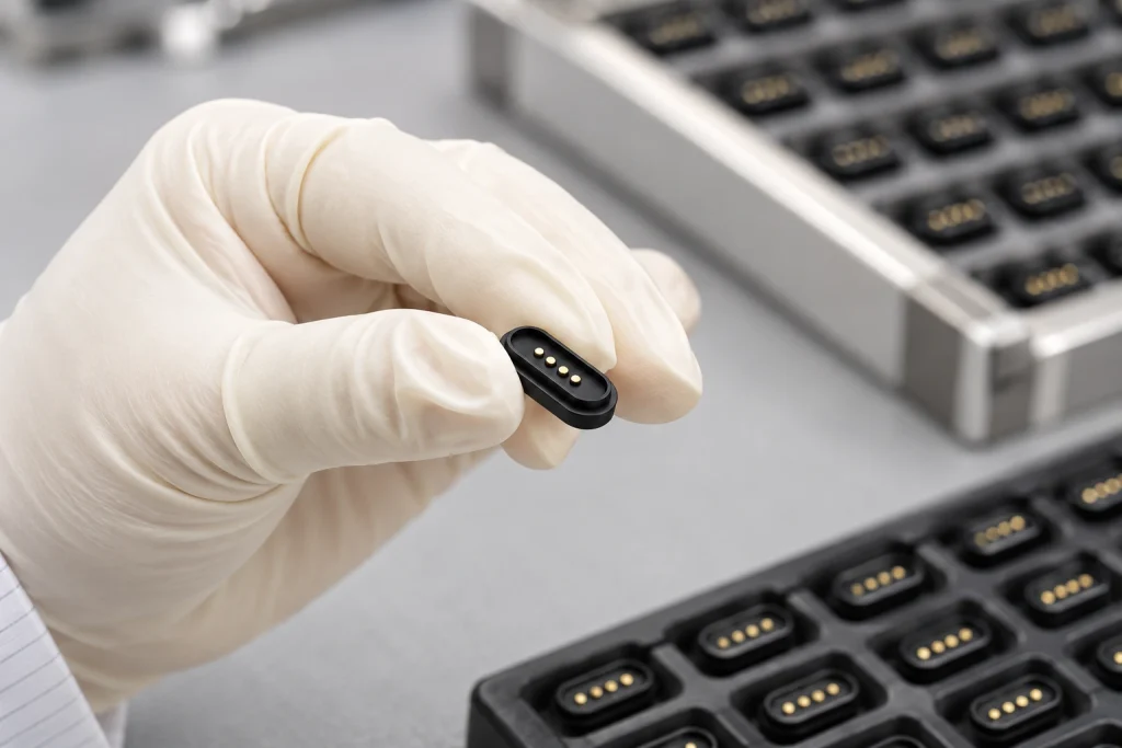
Seven Production Quality Gates
DFM: review the tolerance stack, establish critical-to-quality dimensions and approve the test plan.
Incoming quality: sample magnet flux and polarity, review material certificates and check plating chemistry.
In-process quality: inspect stamping burrs and flatness, molding warp and flash, and plating thickness with XRF.
Assembly: confirm magnetic polarity and placement with gauges, then validate adhesive curing.
End-of-line testing: check continuity on 100% of parts, measure contact resistance according to the plan, and perform insulation or Hi-Pot testing where required.
Reliability: run mating-life, vibration, thermal-shock and salt-spray checks according to the program.
Outgoing quality: complete visual and AQL checks, verify labels and lot traceability, and confirm packaging.
| Checkpoint | Typical method | Frequency (typical) |
|---|---|---|
| Plating thickness | PLATING THICKNESS TESTER | Per lot / per shift |
| Lifespan | LIFE TESTERS | Test based on settings |
| Contact resistance | Milliohm measurement | 100% for critical SKUs; otherwise per plan |
| Pull/holding force | Force gauge | Per lot / sampling |
| Corrosion-resistant | Simulation testing | Batch/Actual Demand Testing |
Scroll horizontally to view every column.
Batch-testing note: the source describes product-batch checks covering durability, salt-spray resistance, high and low temperatures, spring resistance, plating quality, constant temperature and humidity, surface roughness and other relevant characteristics. These are controls intended to prevent defective parts; the final product specification and test plan determine the applicable methods and acceptance criteria.
Magnet control, plating control, precise assembly and testing at defined gates are most effective when they form one coordinated production loop.